
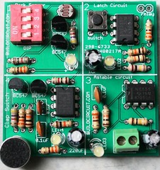
4 in 1 DIY kit schematic
Kit making Photos: http://www.flickr.com/photos/buildcircuit/sets/72157631683001494/
KIT MAKING VIDEOS AVAILABLE ON: http://www.youtube.com/playlist?list=PL0GelaJ0OBT11j43FhrPFlRy5geHVWomL
1. Dark sensor:


Description: As you block light falling on the LDR, the LED D1 switches ON. As soon as you put lights on the LDR, the LED goes off.
Extra experiment: The sensitivity of the circuit depends upon the value of resistor R3. If you replace the resistor R3 (4.7K) with some other resistor, for example 330 Ohm, it becomes highly sensitive to darkness and if you increase the resistance beyond 4.7K, it gets less sensitive to darkness. You can try it.
For more information:
http://www.buildcircuit.com/dark-sensor-using-two-transistors-buildcircuit/
2. Latch Circuit
Description: When you press the tactile switch, the LED D2 switches on and when you press it again, the LED switches OFF. This is bistable mode of NE555 timer.


See how to make this circuit on breadboard.
Extra experiment: You can do a simple experiment with relay also. You can make a light operated switch with this circuit.
The schematic for the circuit is given below:
In this experiment, when you press light falling on the LDR, the relay gets activated and switches on the LED2. Here, relay operates exactly like the tactile (momentary) switch.
3. Astable Mode:
Description: In this experiment, the LED3 blinks according to the values of R3, R1 and C2. It has been configured in the astable mode of 555 timer.


Read more about astable mode: http://www.buildcircuit.com/astable-mode-of-555-timer/
Extra experiment:
You can make an Infrared transmitter with this kit by just changing the values of resistors.
Schematic for IR transmitter is given below:
![]()
Read more about infrared transmitter: http://www.buildcircuit.com/astable-mode-of-555-timer/
4. Clap switch
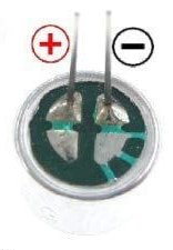
Description: When you clap close to the electret microphone, it switches the LED4 ON for a while and switches off again.
When you clap, the circuit triggers pin 2 of NE555 timer and takes it to monostable mode.
The ON time is determined by the values of resistor R2 and capacitor C1. The timing is 1.1xR2xC1.
You can alter the timing of the circuit by changing the values of resistor R5 and capacitor C1. You can try with 100K and 100uF.


Read more about monostable mode: http://www.buildcircuit.com/monostable-module/

Check out other popular DIY Kits
-
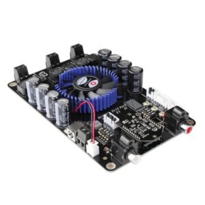
2CH X 100W + 200W 2.1 Channels Bluetooth Audio Amplifier Board – TSA7500
Checkout in our STORE -
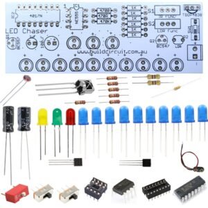
LED Chaser Using NE555, CD4017, Infrared Receiver And Photoresistor
$12.95 Checkout in our STORE -

CD4026- 1 Digit Up Counter Module
Checkout in our STORE -
CD4029 Based Up And Down Counter For Arduino And NE555
Checkout in our STORE -
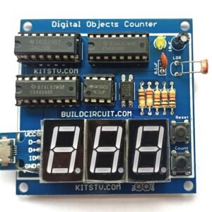
3 Digit Digital Objects Counter With Laser Module
Checkout in our STORE -
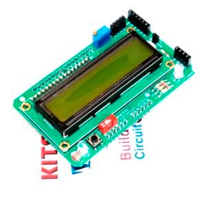
LCD Shield For Arduino-Bluetooth Android Hobbyists
Checkout in our STORE -

1.8″ Photoresistor And Laser Operated Medium Digital Objects Counter
Checkout in our STORE -

Photoresistor And Laser Operated Large Digital Objects Counter With 2.3″ Displays
Checkout in our STORE -
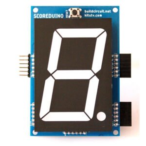
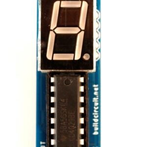
2.3″ Common Anode Seven Segment Display Driver
Checkout in our STORE -
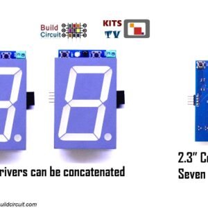
2.3″ common cathode seven segment display driver
Checkout in our STORE -
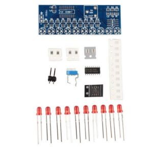
SMD DIY Kit NE555 Oscillator CD4017 LED Chaser Circuit
$4.95 Buy product
Hwwwwoooooooooo