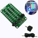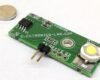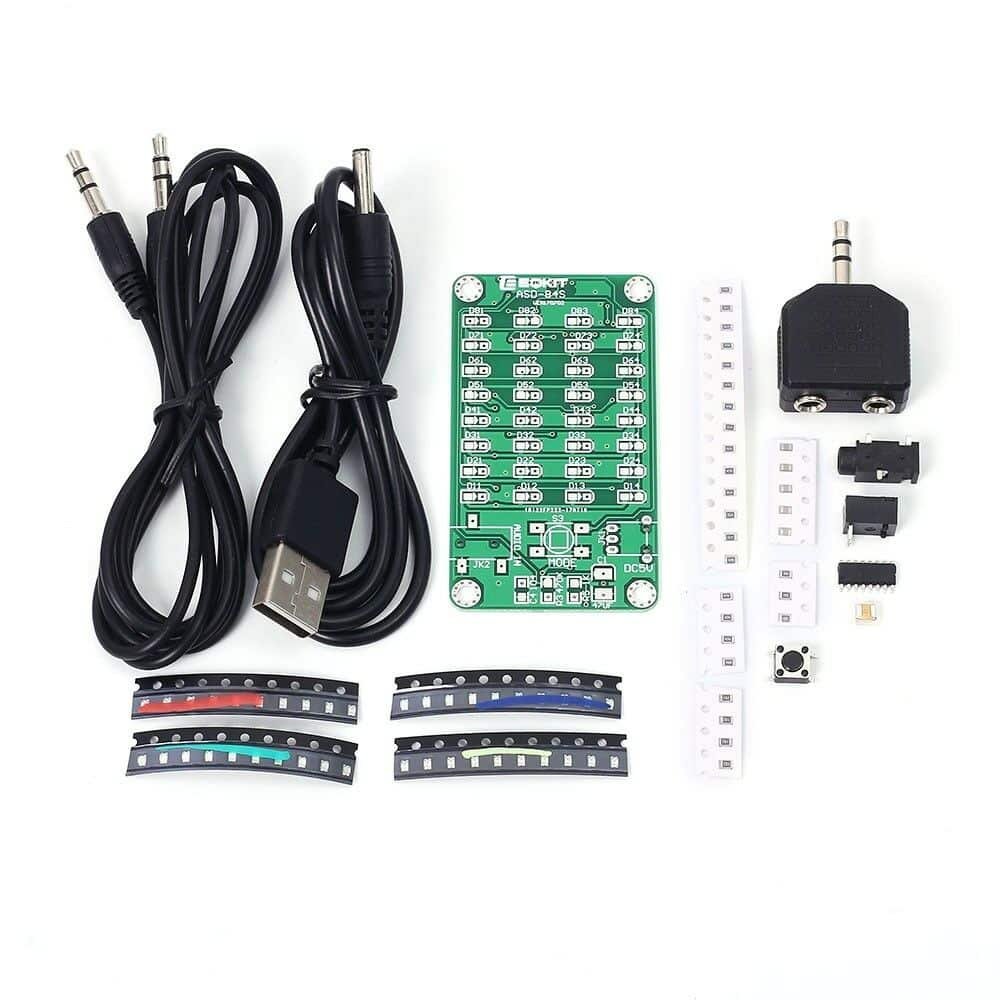
DIY KIT 34- 8×4 Audio LED Spectrum-Music level indicator
This is yet another audio LED spectrum DIY kit. Connect the kit to any audio source and see the lights patterns changing according to the audio signal. 
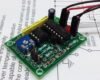
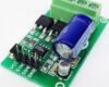
The schematic of the kit is shown below:
 Parameter:
| Parameter | Value |
| Model | ASD-84S |
| Operating Voltage | DC 5V |
| Work Current | <=35mA |
| Standby Current | <=5mA |
| Signal Input Way | 3.5mm Audio Wire |
| LED Color | Red, Green, Blue, Yellow |
| LED Array | line4, row 8 |
| PCB Size | 64.2*36.5mm |
| PCB Mounting Hole | 3mm |
| PCB Hole Distance | 58.1*30.5mm |
| Note: LED should be the same color in one line/row | |
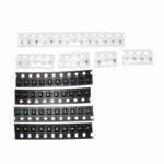
Component List:
| NO. | Name | PCB Silk Screen | Value | QTY |
| 1 | SMD 0805 Resistor | R1 | 10ohm | 1 |
| 2 | SMD 0805 Resistor | RX1-RX4,RY1-RY8 | 47ohm | 12 |
| 3 | SMD 0805 Resistor | R4,R5 | 1K | 2 |
| 4 | SMD 0805 Resistor | R2,R3 | 470K | 2 |
| 5 | SMD 0805 Capacitor | C2-C4 | 0.1uf | 3 |
| 6 | Electrolytic Capacitor | C1 | 47uF | 1 |
| 7 | Contact Switch SMD | S3 | 6*6*5mm | 1 |
| 8 | IC 1084S | U1 | SOP-16 | 1 |
| 9 | Audio input socket | JK2 | SMD3P | 1 |
| 10 | Power input socket | JK1 | 3.5mm | 1 |
| 11 | Red LED | D11-D81 | SMD 0805 | 8 |
| 12 | Green LED | D12-D82 | SMD 0805 | 8 |
| 13 | Blue LED | D13-D83 | SMD 0805 | 8 |
| 14 | Yellow LED | D14-D84 | SMD 0805 | 8 |
| 15 | USB to DC Line | 3.5mm 0.8M | 1 | |
| 16 | PCB | 64.2*36.5mm | 1 |
Operation Method:
| Working Model | Working Model | Display | Function Description | Default Declaration |
| Short Press | Quick refresh speed | 3 | Refresh speed is very quick, very dynamic | 2 |
| Medium refresh rate | 2 | Refresh speed is average | ||
| Slow refresh rate | 1 | The refresh speed is slow and the vision is good | ||
| Long Press | High sensitivity | H | Capable of detecting weaker signals | B |
| Medium sensitivity | B | Able to adapt to most signals | ||
| Low sensitivity | L | Capable of filtering weaker interfering signals | ||
| Press and hold the button first, then switch on the power, get into Factory mode. | ||||
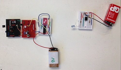
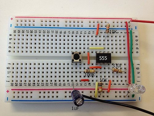
Click on the images below to see all the assembly images. You can see all the images on Flickr also.
Assembly Tutorial from the manufacturer
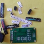


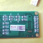


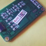
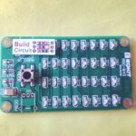

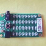

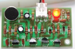
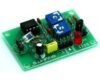
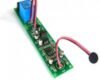
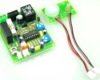
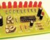
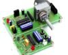
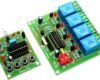
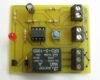
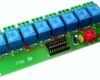
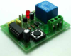
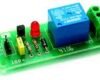
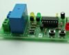
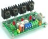
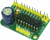
Other images of the kit: