
Description
WARNING: BUYING and USING an FM transmitter is illegal in several countries. Make sure that it is legal to use in your country before you place an order.
https://www.aliexpress.com/item/32735077258.html?spm=a2g0o.productlist.0.0.31327dc8ql08kE&algo_pvid=79235ac7-5cc6-405f-b86c-1a17b520f5a9&algo_expid=79235ac7-5cc6-405f-b86c-1a17b520f5a9-30&btsid=0b0a555716063489205036784e1a21&ws_ab_test=searchweb0_0,searchweb201602_,searchweb201603_
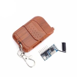
The other small transmitter:
https://www.aliexpress.com/item/32811761994.html?spm=a2g0o.productlist.0.0.1c922b9b2k7AeP&algo_pvid=c14a42e6-b638-40e0-8510-9c5c0ae4bcb3&algo_expid=c14a42e6-b638-40e0-8510-9c5c0ae4bcb3-8&btsid=0bb0623916063505111282156e55e5&ws_ab_test=searchweb0_0,searchweb201602_,searchweb201603_
Transmission range: 100-200meters.
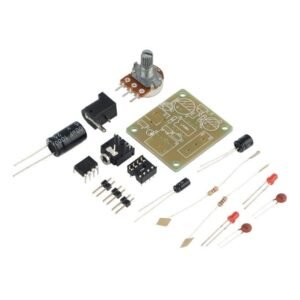
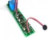
This is yet another basic FM Transmitter using 3 transistors. This is a learning kit for electronics beginners and hobbyists who want to learn about FM transmission as well as soldering. Basic soldering is enough to build this transmitter. It should take about half an hour to make a perfectly working FM transmitter.

Features:
- Transmission range: 100m-200m (depending upon antenna length, test environment, power supply, and FM receiver )
- Audio and voice transmission: Transmit both audio or voice. The audio signal can reach 100m-200m depending upon the antenna of the receiver and used environment. For example, if you transmit from a higher building keeping the antenna by your window, the signals easily reach up to 200m or even more. It is highly recommended that you test the transmitter in the open ground/space where there are no buildings or any other obstacles. You need to buy a stereo jack separately to connect to the 3 pins male header to transmit audio. The stereo jack is not included in the package.
- First test: You can test the transmitter immediately after you assemble it. You can use any general FM radio. You should hear a feedback noise when your transmitted signal matches with the reception frequency.
- Frequency range: 88Mhz-108Mhz.
- You cannot adjust the frequency. If your transmitter is transmitting at 88.9Mhz and there is also a commercial FM transmitting at the same frequency, your transmission will overlap the commercial broadcast(to some extent, up to 200meters). When you go away from the transmitter (more than 200 meters), the commercial broadcast will again take its frequency. If you want a transmitter with variable frequency, then this is the right transmitter(long-range transmitter) for you.
- You can adjust the volume using the potentiometer.
- Antenna: if you use 20cm wire as an antenna, it can transmit up to 100m. With 40cm, it can transmit up to 200meters.
- Operating voltage: 1.5V-9V. We have tested using a 9V battery.
- Operating Current:3.3-29mA
- Audio Response:20Hz-15KHz
- Radio Frequency Power:-2dBM~15dBm
- Radio Frequency Output Impedance:50 ohm
- Board Size:50*30mm
- The Second Harmonic:>=-40dB
- Receiver Devices: General FM radio/cellphone which has FM radio function/Car FM radio(Recommended for testing)
Assembly tutorial
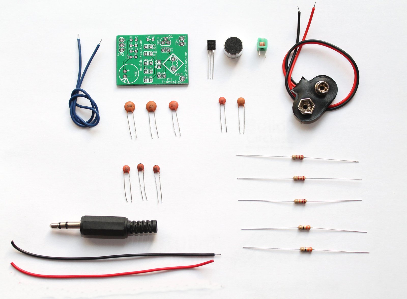
Components included in the package:
- 1 x PCB
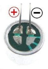
- 1 x Electret Microphone
- 1 x Antenna wire. Should be at least 10-20cm long.
- 1 x 3 pin male header.
- 1 x 500K potentiometer. Make sure it is turned in full to transmit the full volume signal.
- 1 x 33uF electrolytic capacitor. Be careful with the polarity while soldering. See the video and all the images published on this page.
- 1 x 4.5T inductor
- 2 x 5.5T inductors
- 1 x S9014 transistor. (be careful, don’t replace S9014 with S9018)
- 2 x S9018 transistors (be careful, don’t replace S9018 with S9014)
- 4 x 0.1uF ceramic capacitor (code: 104)
- 1 x 0.01uF capacitor (code: 103)
- 4 x 30pF (code: 30)
- 2 x 680pF (code: 681)
- 2 x 10pF (code: 10)
- 3 x 2.2K resistor (Code: Red-Red-Red)
- 2 x 22K resistor (Code: Red-Red-Orange)
- 1 x 1M Ohm (Code: Brown-Black-Green)
- 4 x 33 Ohm (Code: Orange-Orange-Black)
What do you need to arrange yourself ?
- Stereo audio jack- to connect from an audio source to the transmitter. Connect the stereo jack to the 3 pins header on the PCB.
- 9V battery connector or any other kind of battery holder to power up the transmitter
- 1.5V-9V battery
- Any FM radio with a telescopic antenna.
Not working? This is how you troubleshoot.
- Check the transistors: There is a high chance that you soldered the transistors in the wrong spots. There are three transistors and all look the same. Make sure that you soldered S9014 and S9018 in their right spots. Watch the video once again.
- Look at the back of the PCB, make sure there is no short.
- The electret microphone polarity could be wrong.
- The battery connector could be connected incorrectly. Make sure that you didn’t connect the positive terminal of the battery to negative and vice versa.
- The 103(10K)potentiometer could be turning off the volume completely. Make sure the volume is turned on completely.
- Resistors soldered incorrectly. Watch the video once again.
- Check the polarity of the capacitor.
If the transmitter is working, you would get feedback from the FM radio.


Reviews
There are no reviews yet.