Dark sensor using two transistors
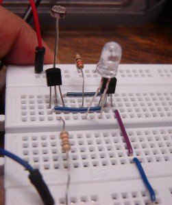
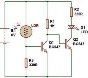
This works same as the other dark detector circuit. When light is falling on LDR, its low resistance drives transistor Q1-BC547 into conduction. This keeps transistor Q2 cut-off due to low base bias. The D1-LED does not get power as long as ambient light falls on LDR. When the resistance of LDR becomes high in darkness, transistor Q1 stops conducting and transistor Q2 starts conducting to turn on the D1-LED.
Datasheet of BC547: http://www.datasheetcatalog.org/datasheet/fairchild/BC547.pdf
Click the video below to see the output.
Components for this experiment are available at buildcircuit.net.






nice…. thanks alot,,
keep update me yah
is it BC147 or BC547? by the way, are they the same?
Yes, both are same. even BC548 is also same. You should datasheets to see the alternative of a transistor. It says BC546/547/548/549/550 are all same. Please check here: http://www.datasheetcatalog.org/datasheet/fairchild/BC547.pdf
this is not working..wtf..
manloloko kau..gumawa naman kau ng gumagana.
Hi. This is work.
But I still confused why when we use only
one transistor with the same ldr and r3 position,
and we add led near r1,
the circuit be light sensor not dark sensor.
I mean reverse.
tx.
thanks for this circuit! 🙂 this works but the other one which you only use one BC547 didnt work. will this circuit can last and a reliable one? because i will replace the LED with a buzzer in short im doing an alarm, also I did parallel connection of 1000micro farad capacitor with the buzzer/led to last longer, and having an input of 9V battery.
i used LDR ….for sun light detection…but ldr only sense the tourch light….what can i use in place of ldr….i used 555 timer for switching purpose…reply
read my name… 😀
it is not working for me..
i have construct exactly same as shown but my LED keep lighting..
pls help..
Can you send me a photo of your circuit? Please use short wires and it should be very clear. send me at email@buildcircuit.org
Hi Sagar,
even i connected the same way but,my LED keep lighting..
pls help.
This draws power from my battery even when its off so by the time its night time it will be dead is there anyway around this with a diode etc?
I have the same problem as khalienz, and iwant to make sure with you, if bc 147 is same bc 547, then why the Ic(collector current ) are not the same, BC147 is 200mA and BC547 is 100mA..could this be the problem??..sorry i’m a beginner, anyway it’s a cool project, i like it
any answer? same problem
nw i knw it works only in sunlight …..tell me how to inc the senstivity
Hi Sagar, Thanks for the dark detector circuit its great work. Q. I would like increase the voltage from 6V to 24V, how would this effect the circuit resistors R1,R2, and R3. which size should I select ? Many thanks Richard.
hi like it. Works but have to be very close with light to turn off led is this normal .got a neat idear for this got a windmill in garden with lots of small windows and a solar light .
Hi i got this working but i want to add an alarm to it .
how to go about it???
hell yeah it works 😀 🙂 tque admin 🙂
Where is a parts list and how much did this cost to build?
Dear sir, i want to use this circuit to create a “smart” toy car, so when the light is off (like when passing your hand over the lrd) it starts running, is this powerful enough to ignite a dc motor like those in the toy cars?
Or it better to use the other circuit with just 1 transistor?
regards
i already tried use the same circuit but i didnt use BC547. I change it to BDX33C, the result is the same but the light is not totally off when i expose LDR to the bright light. and LED keep lighted eventhough i test it on my desk with light open. it need to get exposed to a very bright light but it’s not totally off. is there any problem when i use BDX33C instead of BC547??? please help
Dexplain the working and princeple application ,advantage , disadvantage of the dark sensor
Gaje Singh
9416629025
Voltage between D1 LED ?
I want to power a LED using about 5v and 200ma. any changes to achieve this ?
can you show me your waveform output and input please ..