


Dark sensor using transistor, phototransistor and photodiode
Description: This versatile dark sensor is made up of two transistors. It is a versatile module, because you can use it for testing several electronic components, such as, relay, reed switch, light dependent resistor(LDR), electret microphone, phototransistor, photodiode, etc. Besides, you can use this module for making simple clap switch, light operated switch, water level indicator, etc.
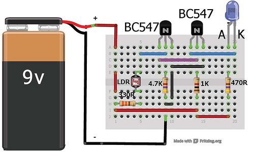
Experiment 1: Dark sensor using Light dependent resistor(LDR).
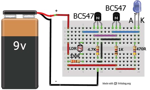
THIS CIRCUIT WORKS WITH 9V ALSO.
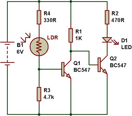
When you block the light falling on LDR, the transistor Q1 switches off and transistor Q2 switches on, that drives the LED D1. Change the value of R3 to change its sensitivity.
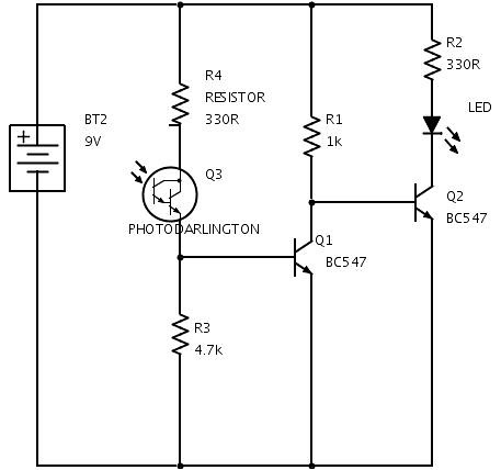
EXPERIMENT 2: DARK SENSOR USING PHOTOTRANSISTOR
For testing a phototransistor, just replace the LDR with a phototransistor, it simply works.
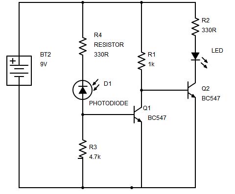
EXPERIMENT 3: DARK SENSOR USING PHOTODIODE
For testing a photodiode, just replace the LDR with a photodiode, it simply works. Anode of photodiode should be connected to base of transistor Q1(as shown in Figure below).
Schematic made using SchemeIt.
WATCH THE VIDEO:
EXPERIMENT 4: RELAY TEST
🛠️ Dive into our collection of DIY Kits, 🔊 Audio Amplifiers, Digital Scoreboards, FM transmitters, and more!
🎶 Explore endless possibilities at our new store.


hi, how long does the 9volt battery last for the ldr setup? say i put it in patio and when it gets dark it turns on until dawn, runs for 10hrs a day, thanks
Its better if u can use an ac-dc adaptor.. U cant trust a 9 V battery.. I have seen battery which burns off in a flash
Can I make the dark sensor circuit using solar cell instead of photodiod?
“Can I make the dark sensor circuit using solar cell instead of photodiod?”
I believe you could do so. Take the output of your solar cell and feed it into the gate of a mosfet. And to make things simple, place the MOSFET where the photodiode is in the circuit above.
How to enhance the dark/light sensor into a miniproject
I did everything step by step, I sure that curcuit is right, but its always switch on, on the dark and light
i know i doesnt sound good .. bt please tell me what is the need of a transistor ????
Well its always good to ask question.. If u get to analyse the circuit u could understand it a bit. The principal of the input of the transistor(Base-Emitter) is forward biased and the output is reversed biased is used here. Whenever the current gets the Base Emitter part of the transistor is flows through ease due to lack of much resistance bt current only flows from collector to emitter when the current is strong. e.g. when the led is lit in that case current does flow from collector to emitter because the current will be high which you will understand why if you analyse the circuit.
I made the circuit……its on a vero board…..its always switched on and also not changing on ldr please tell what can i do….THANKS
hello sir i’ve tried the dark sensor using ldr project and assembled the circuit exactly in the same way as in the video.however the led remains on irrespective of whether the ldr is in the circuit or not. where am i going wrong??
Sir, I connect the circuit properly but led is always on either the LDR is circuit or not. what can I do.
Thanks, its work but slightly change in resistor value.
4.7 k resistor replace with 1 k and enjoy the moments.
Pur si simplu perfect. Dark sensor using transistor, phototransistor and photodiode merita
distribuit pe facebook. curs valutar
Can i know what photodiode is using? I mean, what is the code number for that photodiode?
You can use any kind of photodiode. Any kind of photodiode works for this experiment.
Sir, I connect the circuit properly but the led is always on either the LDR is in the circuit or not. what can I do.
Hi this is a very simple & a great circuit…..bt can you please explain me steps by step procedure in designing & choosing the value of components for this circuit ?? i know we can use any transistor that just need to be biased properly bt i always wonder how to bias it at the req. operating point ?? the exact procedure…..
As with Arsalan and Abdullah, this did no work for me exactly as depicted for Experiment #1.
I used two BC547C transistors, and one of the smaller photocells from a variety pack that sold at Radio Shack (Cadmium-Sulfide Photocells).
I had to use a 2.2 K resistor instead of the 4.7 K, as is depicted under the left transistor on the layout. No big deal, but that was not obvious to me. For others, Sagar Sapkota mentions this as an adjustment to R3 in the verbal description. When I use the larger Cadmium-Sulfide Photocell from Radio Shack, it will run from either the 2.2 K resistor or the 4.7 K resistor.
It is not using much in the way of Amps, using about 3 volts for the LED light, and about 7.2K Ohms, meaning the Amps are around 0.4 milliamps. That should run for about forever on that battery. (I am using a 9 volt rechargeable that is currently putting out about 8.5 volts.)
I’d like to charge during the day, and emit light at night, so I am looking forward to reviewing your relay posting.
Thank you, that was fun.
– Dave
I tried the light sensor circuit,it worked in first attempt.thank you sooooo much!!!!!