DIY KIT 17- DIY ZIF Arduino programmer

It is just another ‘build your own Arduino’ project. BuildCircuit has worked on similar projects before. The most popular project is a DIY Arduino kit. The DIY Arduino looks similar to the real Arduino boards and uses an FTDI basic programmer to program the chips.

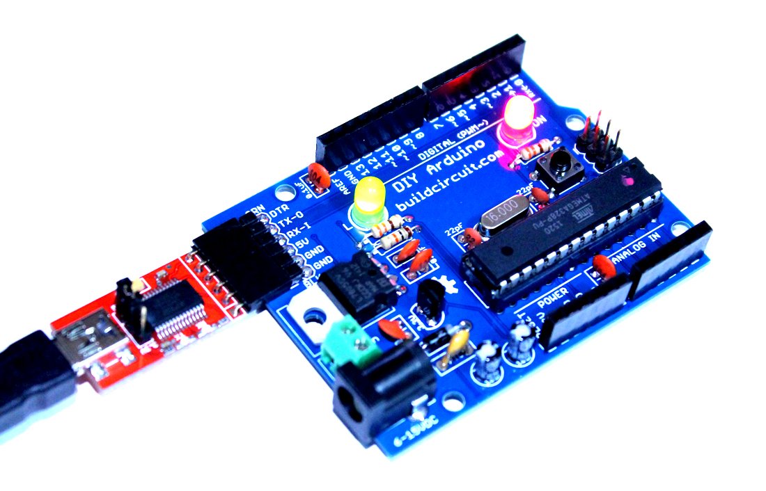
The kit that we are going to work on this article is also a DIY Arduino. It comes with a zero insertion force (ZIF) IC socket. You can simply insert an Arduino chip and program it. The board has a header to connect an FTDI basic module that can be used to program the Arduino chip.

(more…)

How to program Amarino lamp

Recommended app

To know about Amarino lamp, visit this page. 

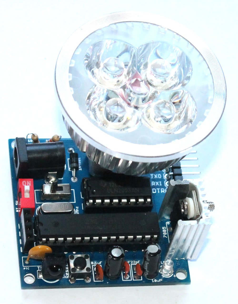
Amarino lamp is fully programmable. The kit package consists of FTDI basic breakout board, you can use it to program the lamp. The lamp is based on Arduino.

Connect the FTDI basic breakout board to the lamp, open the Arduino programming interface and upload your sketch.

REMEMBER: Turn off the red colored 1P DIP switch 1-position-2p-side-style-dip-switch-redwhile uploading sketch(if the Bluetooth module has been stacked over the 4 pin female header)

programming

Documents: 

  1. About Amarino Lamp
  2. Assembly Tutorial
  3. Amarino Lamp- Light sensor
  4. Lamp test with different phone sensors
  5. How to program Amarino lamp

Where can you buy ?

buildcircuit    etsy

Build a simple DIY clap switch

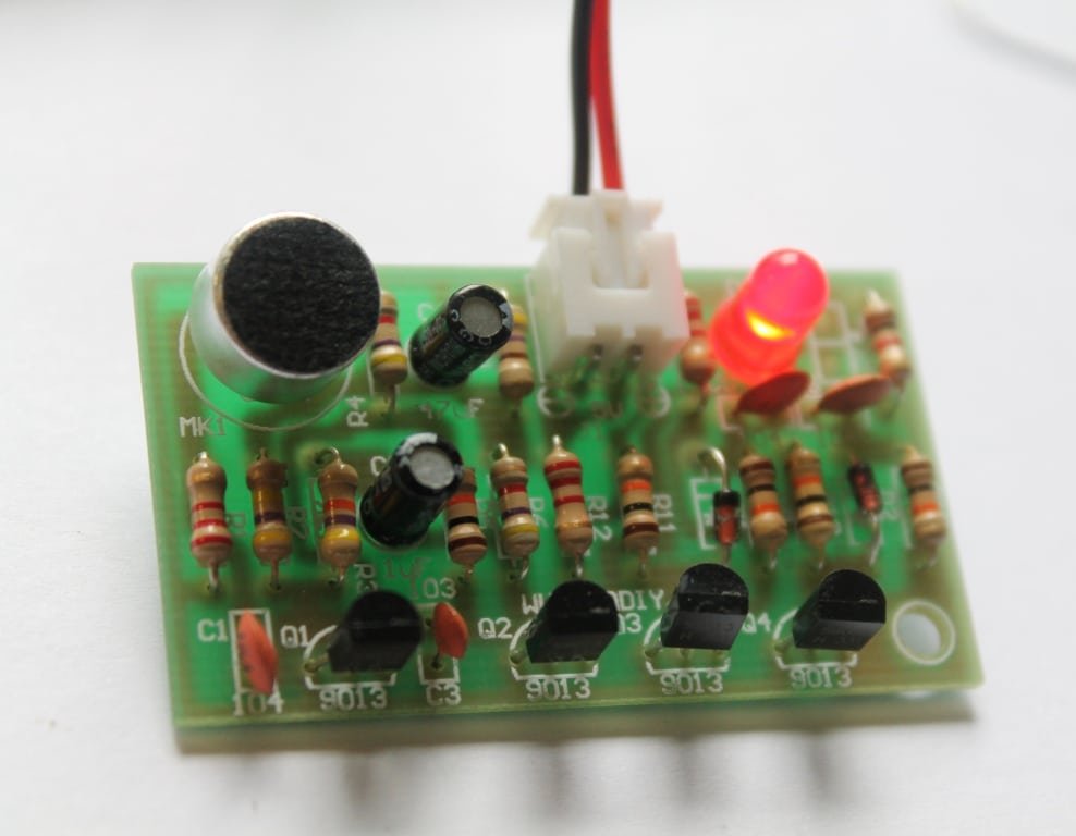
Description: Here’s a simple DIY clap switch circuit. The circuit is mainly composed of an audio frequency and a bistable trigger circuit.

Q1 and Q2 together form an amplifier circuit. MK1 (electret microphone) accepts Clap/Audio signal and that enters to transistor Q1 through the coupling capacitor C1 and enters to Q2 base through collector directly after getting amplified. And it obtains a negative square-wave which used to trigger the bistable circuit from Q2’s collector.  (more…)

Assembly guide- DIY Arduino

We are now selling the BLUE COLORED DIY Arduino kit

This post shows you how to assemble the DIY Arduino board.

DIY Arduino Kit for Beginners (8)

The assembly process is straight forward. It can be easily assembled if you follow the silkscreen indicators(labels) and have beginning experience with a soldering iron. You will need to read the resistor bands or use a multimeter to determine the resistor sizes.

Note: You will need either an FTDI Basic or FTDI cable to load code using the Arduino IDE.

Kit Includes:

  • 1 x Arduino-Compatible plated through holes (PTH) Kit PCB
  • 1 x ATMega328 with Optiboot bootloader
  • 1 x L78L33 3.3V Voltage Regulator
  • 1 x 5mm Green LED
  • 1 x 5mm Red LED
  • 2 x 330Ohm Resistor
  • 1 x 10kOhm Resistor
  • 1 x 16MHz Crystal
  • 2 x 22pF Ceramic Capacitors
  • 5 x 0.1uF Ceramic Capacitors
  • 2 x 10uF Electrolytic Capacitors
  • 1 x LM7805 5V Regulator
  • 1 x Diode 1N4001
  • 1 x Resettable Fuse PTC (300mA)
  • 1 x 28-Pin DIP Socket (To seat your ATMega)
  • 1 x Push Button Reset Switch
  • 2 x 6-Pin Female Headers
  • 2 x 8-Pin Female Headers
  • 1 x 6-Pin Right Angle Header (To connect your FTDI Basic)
  • 1 x 0.1uF Capacitor
  • 1 x DC Barrel Jack
  • 1 x 2-pin screw terminal
  • 1 x 6 pin ICSP header

Description of this DIY Arduino board is available on this page.

Assembly video: 

See all the assembly images on Flickr

You can see all the assembly steps on this post.

Step 1: Start with the resistors 10K(Brown-Black-Orange) and 2 pcs 330R (Orange-Orange-Brown).

1 Fix all the resistors

You can see all the assembly steps on this post.

Step 2: Then fix the 16Mhz crystal oscillator, 1N4001 diode and 2pcs of 22pF capacitors.

4- Fix 22pF capacitor

You can see all the assembly steps on this post.

Step 3: Fix 5 pcs of 0.1uF capacitor. The image shows only 4pcs. I actually forgot to solder the last one, which is right after the Vin point.

5- 4pcs of 0.1uF capacitor-another angle

capacitor

The left over(remaining) 0.1uF capacitor

Step 4: Solder LM7805 voltage regulator, 3.3V regulator and the tactile switch.

8- fix 3.3V regulator

You can see all the assembly steps on this post.

Step 5: Now fix the PTC resettable fuse (300mA), 28pin IC header, 2 pin screw terminal and 2pcs of 5mm LEDs.

11- Fix 28 pin IC header and the LEDs

You can see all the assembly steps on this post.

Step 6: Fix the DC barrel, 2 pcs 10uF capacitors, 6 pin male header (for connecting FTDI basic module) and ICSP header.

17- close up

Step 7: Finally, fix the stackable headers and Arduino UNO chip. Your Arduino is now ready.

19- The DIY arduino is now ready

You would need a FTDI basic module to program the Arduino board. The following image shows how to connect the FTDI basic module.

21- FTDI connection to Arduino and computer

You can see all the assembly steps on this post.

See all the assembly images on Flickr

See the output below:


You can purchase this kit from here:

BC-2138

Do-It-Yourself (DIY) Arduino- Make Your Own Arduino

US $14.95
This kit contains everything you need to build

Assembly- Breadboard power supply DIY kit

button_prev_page

This is the assembly tutorial of ‘breadboard power supply DIY kit’. You can get all the details of this kit at this link.

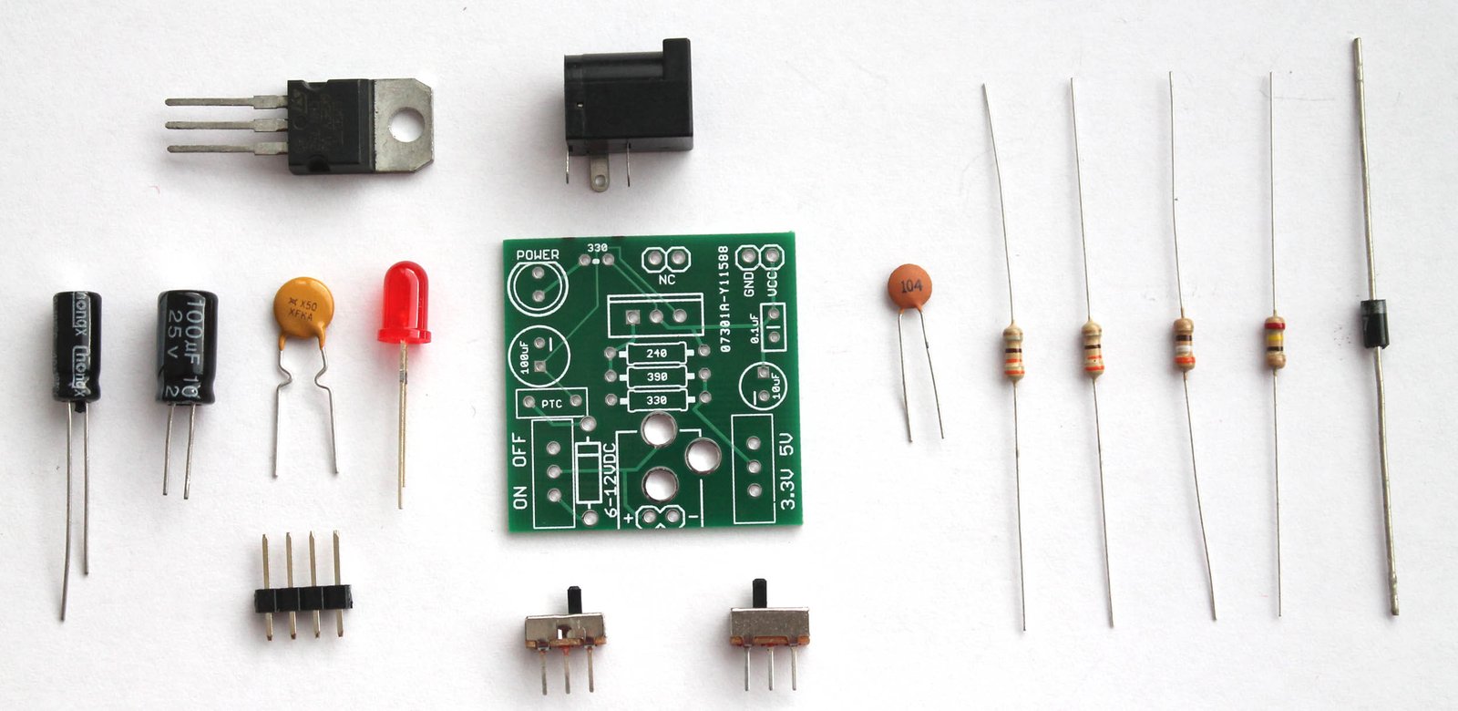
You will get the following components with the kit package. You can purchase this kit at buildcircuit.com.au. The web store is operated by BuildCircuit team.

Breadboard power supply- components

try this also

Look at the PCB below.You can see the silkscreen indicators/labels of the components. If you follow the labels correctly, you can easily assemble all the components on to the circuit board.

PCB

PCB dimension: 31.75mm x 31.75mm

Step 1: Start with resistors. Solder the three resistors- 330R, 390R and 240R. Click on the resistors to get the color code.

Step 1- solder resistors 330R, 240R and 390R

Step 2: Then, fix the diode 1N4001. You can also use 1N4004 or 1N4007. All work the same way.

Step 2 Solder 1N4007 diode

Step 3: Fix 0.1uF (code-104) capacitor.

Step 3 Solder 0.1uF capacitor

Step 4: Fix the 2pcs of SPDT switch. One switch is for ON/OFF function and the other is for switching 3.3V and 5V.

Step 5 Solder another SPDT switch

Step 5: Fix the 5mm red LED. It works as a power indicator.

Step 6 Solder 5mm LED

Step 6: Fix the PTC resettable fuse (500mA). This is a handy little device that can save your system from burning. A resettable fuse (also known as a PTC) is a resistor that has very unique properties.

For this kit, if your circuit tries to draw more than 500mA of current (if you have a bad short for instance) the PTC would ‘trip’ (by heating up). The increased resistance (trip state) would break the circuit and allow only a small leakage current.

Step 7 Solder resettable fuse 500mA

Step 7: Solder the 330R resistor. It works as current limiting resistor for the 5mm LED.

Step 8 Solder the last 330R resistor

Step 8: Solder 100uF and 10uF capacitors. Please be careful with the polarity. Wrong polarity will burn the components. The silkscreen indicators should help.

Step 9 Solder 100uF and 10uF capacitors

Step 9: Solder the LM317 chip and DC barrel.

Step 10 Solder LM7805 and DC barrel

Step 10: There are 2pcs of 2-pin male header for fixing the circuit board into the breadboard holes. You need to solder them as shown on the image below.

Step 11 Solder the male headers for breadboard

Give a close look.

Step 11-Close up

Step 12: Fix the power supply into your breadboard using the male headers. Power up the circuit with any DC supply (6-37V), it will give two outputs- 3.3V and 5V(one at a time).

Step 14- 3 Powering up the breadboard power supply - Copy

The kit is ready to use for your projects. Fix your project components on the remaining part of the breadboard.

Step 13 Powering up the breadboard power supply

Recommended links:

  1. How to make power supply using LM317 ?
  2. Assembly Tutorial
  3. Buy the kit at buildcircuit.net
  4. Video- How to make a LM317 power supply
  5. Images on Flickr
  6. Schematic-breadboard-power-supply

You can buy this wonderful DIY kit at buildcircuit.net. BuildCircuit.ORG is the online store owned and operated by BuildCircuit team.

try this also

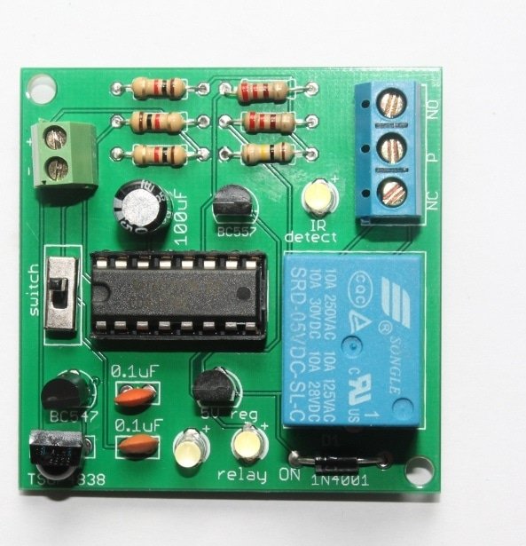
Remote operated switch DIY kit

Description: Here’s a simple do-it-yourself (DIY) remote operated switch. You can use this simple kit to switch ON/OFF any appliances working on 220V AC. This DIY kit has been designed basically as a learning kit rather than as a household device. With this kit, you may learn about relay and infrared sensor. It can used for fun at home for switching appliances operating on 220V AC. (more…)

4 in 1 DIY kit- dark sensor, latch circuit, astable multivibrator and clap switch

This is a simple 4-in-1 do-it-yourself (DIY) kit from BuildCircuit. The kit has four different circuits that can be switched on separately or together at a time using a DIP switch.

The four circuits are:

1. Dark sensor using LDR.

2. A latch circuit using NE555 timer.

3. Astable circuit using NE555 timer.

4. A clap-switch circuit using NE555 timer.

Besides these 4 circuits, by changing the values of the resistors and capacitors, you can change the behaviour of the circuits. (more…)

Search for products

Back to Top
Product has been added to your cart