


Assembly Tutorial- 3 Digits – Digital object counter DIY kit


 This page shows you how to assemble three digit digital object counter. If you are looking for 2 digit digital object counter please see this page.
If you are interested in knowing about this 3 digit counter, please check this page.
The counter module kit package comes with all the components required to build your kit. Before you proceed, please check if you have all the required components:
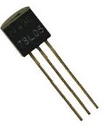
- 1 x TO-92 5V Voltage Regulator(78L05)
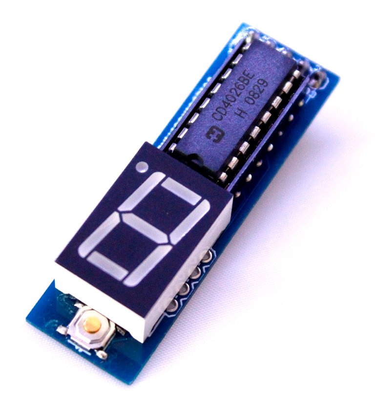
- 3 x CD4026 Decade counter
- 3 x 16-pin IC socket.
- 3 x common cathode seven segment display-(Can be in red, yellow and blue colors)
- 1 x TSOP4838 Infrared sensor
- 1 x 100uF Capacitor- (Voltage rating can be between 16V to 50V- causes no problem in operation)
- 2 x 0.1uF 50V ceramic Capacitor
- 2 x 3mm LED- (can be any color)
- 1 x BC547
- 1 x BC557
- 1 x SPDT Slide Switch
- 1 x Tactile reset switch
- 1 x Screw terminal- (can be in blue/green colors)
- 4 x 1K Ohm Resistor 1/4W
- 1 x 330R Resistor 1/4W
- 1 x 10K Ohm Resistor 1/4W
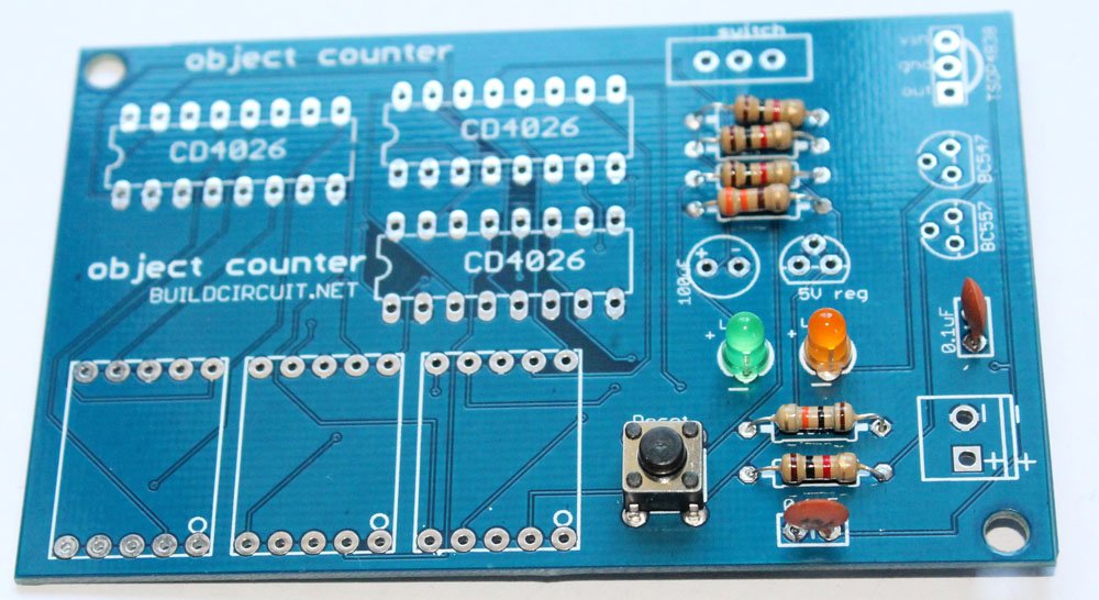
- 1 x Bare PCB with Silkscreen Indicators
- 1 x 9V battery connector
Please follow the following steps:
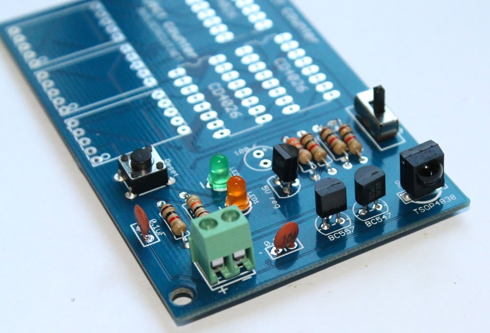
Step 1: Solder 1K Ohm resistors. The color code of 1K ohm resistor is Brown-Black-Red
Click on the image to see the color code more clearly.

Step 2: Solder 10K Ohm resistor and 330 Ohm resistors. The color code for 10K Ohm resistor is Brown- Black- Orange and color code of 330 Ohm resistor is Orange-Orange-Brown.

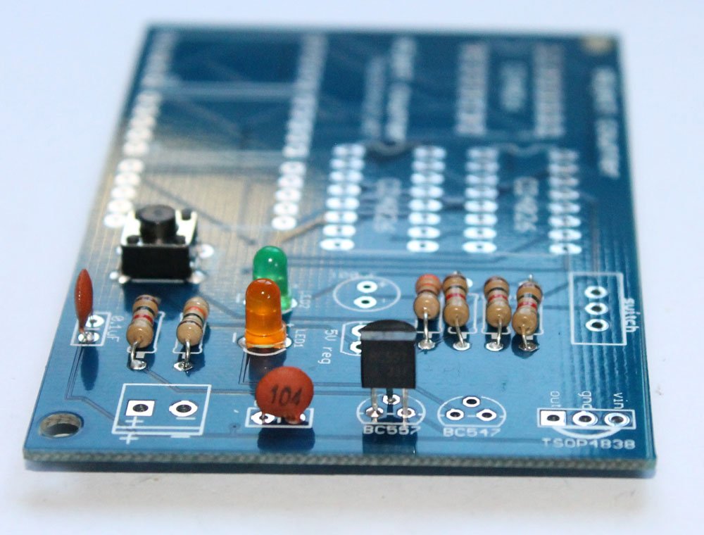
Step 3: Solder 2pcs 0.1uF (code- 104) capacitors.

Step 4: Solder 2pcs 3mm LED. If you do not know which pin is Anode and which is cathode, please see this. The longer pin is Anode and the shorter pin is Cathode.

Step 5: Solder tactile switch. The switch is for resetting the counter. You can see how it work on the video below.
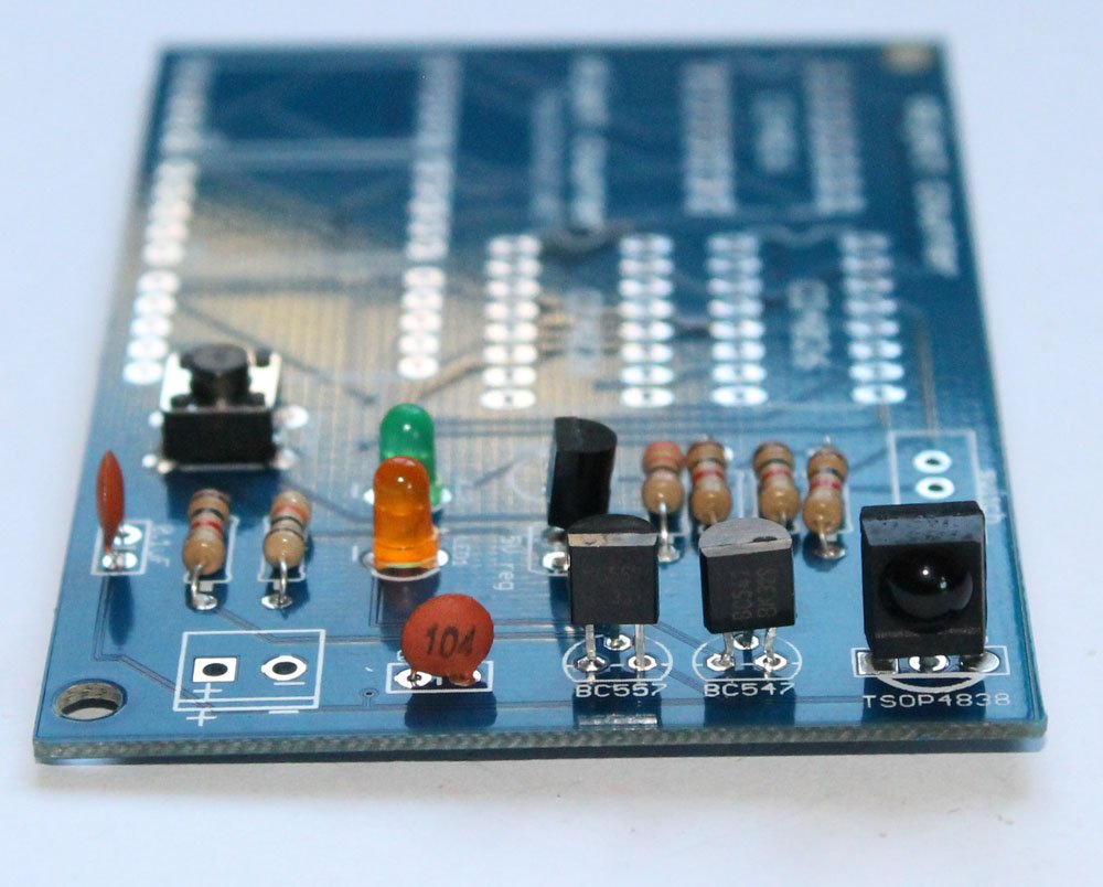
Step 6: Solder BC557 PNP transistor.
Step 7: Solder BC547 NPN transistor
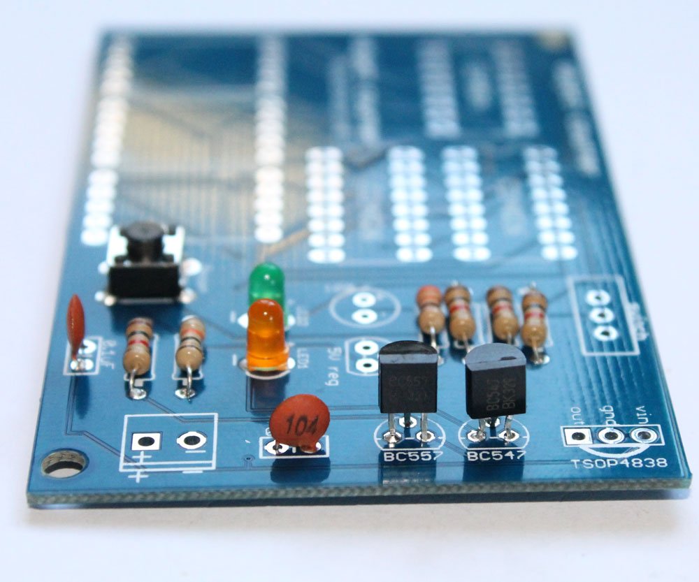
Step 8: Solder 5V voltage regulator. The 5V regulator chip is marked as 78L05. It is in TO-92 package.
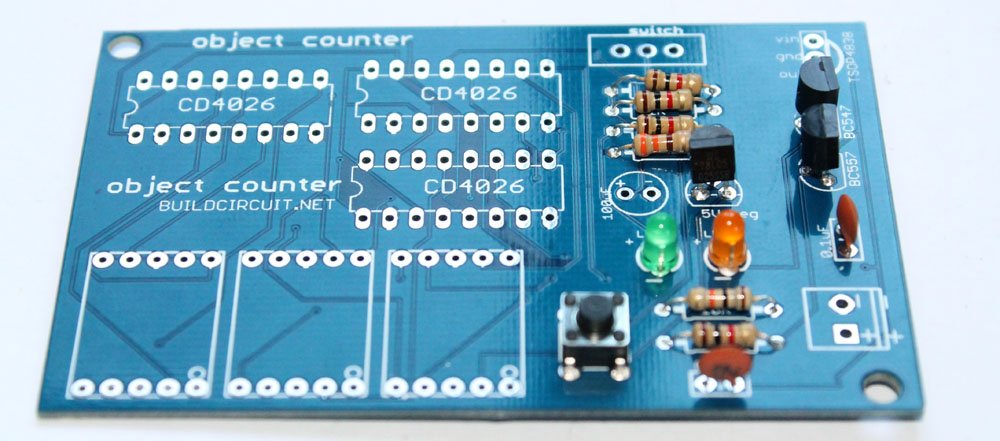
Step 9: Solder TSOP4838 infrared sensor.
Step 10: Solder SPDT switch. It is used for switching ON/OFF the counter module.
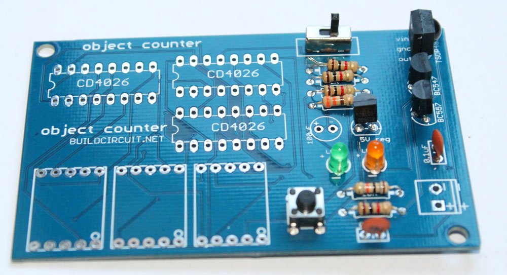
Step 11: Solder 2 pin screw terminal. It is used for connecting a 9V battery to the counter module.
Step 12: Solder 3pcs of 16 pin DIL sockets. These are used for stacking CD4026 chips. 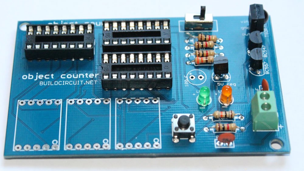
Step 13: Solder three seven segment displays and 100uF Capacitor. Please notice the + and – terminal of the capacitor. Solder it correctly.
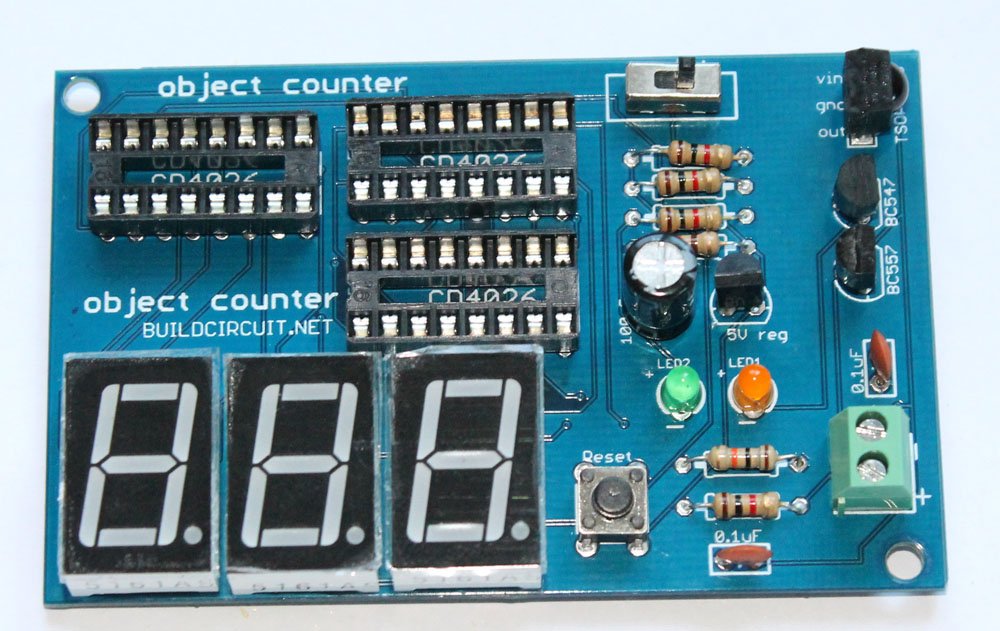
Step 14: Put CD4026 chips over the DIL sockets.

Step 15: Use a 9V battery to operate the kit. Your kit is now ready to use.
Other related tutorials:

🛠️ Dive into our collection of DIY Kits, 🔊 Audio Amplifiers, Digital Scoreboards, FM transmitters, and more!
🎶 Explore endless possibilities at our new store.


