


Clap switch using 3 different modules

Description: In this clap switch we use three different modules given below. It is necessary to make these three modules in order to make a clap switch.
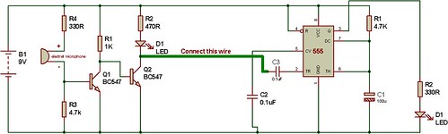
a. Dark sensor using 2 transistors.
b. Monostable mode of 555 timer.
c. Toggle switch using 555 timer.
Now, follow these steps:
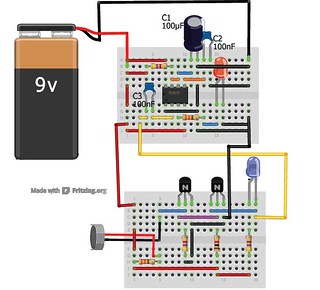
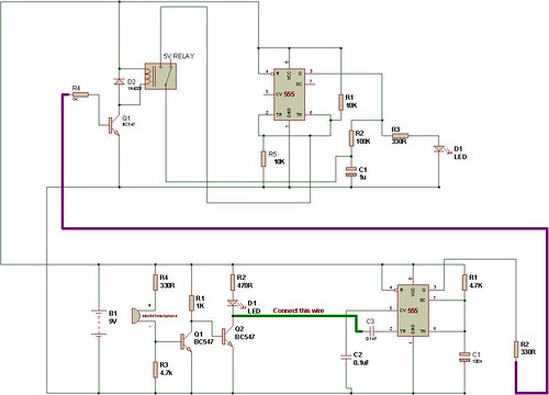
Step 1: Connect 555 timer dark sensor (monostable module) to 2 transistors module.
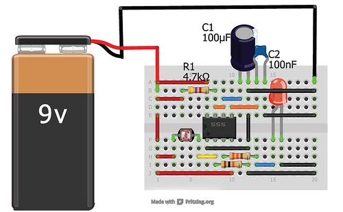
Remove LDR and resistor 4.7K (connected between Pin 2 and GND) from 555 timer based dark sensor circuit(given above).
Step 2: Connect a 0.1uF(100nF) capacitor to pin 2 of 555 and collector pin of transistor Q2.
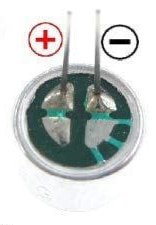
Step 3: Remove LDR from ‘2 transistors module’ and connect an electret microphone. HOW TO CONNECT AN ELECTRET MICROPHONE?
THIS MAKES A BASIC CLAP SWITCH. Change the values of resistor and capacitor on 555 timer to change the timing of the circuit.
PLEASE IGNORE THE REPEATED NAMES OF COMPONENTS. TRY TO SEE THE PROJECT IN SEPARATE MODULES
WATCH THE VIDEO:
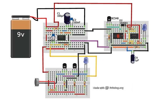
CLAP SWITCH USING TOGGLE SWITCH
Using a toggle switch in the clap switch would offer two stable states for the circuit. On first clap, the circuit switches ON and on another clap, it switches OFF. However, for that, the resistor and capacitor of the monostable mode circuit should be set in such a way that it short pulse of 1 seconds only.
The Monostable circuit given on this page is suitable for the next clap switch circuit.
<

Buy clap switches at BuildCircuit Store

🛠️ Dive into our collection of DIY Kits, 🔊 Audio Amplifiers, Digital Scoreboards, FM transmitters, and more!
🎶 Explore endless possibilities at our new store.


10 QQQQQQQQQQQQQQQQQQQQQQQQQQQQQQQQQQQQQQQQQQQQQQQQQQQQ that is perfect
The components required are not given. can you mail me
The components are given on the schematic. Those are the required components.-
Nice circuit, working perfectly. Can you tell how to use it for ac 220V bulb.
check here: http://www.buildcircuit.com/clap-switch2
Sir,
5V realy not avelable in my local market.
Can i use 6V realy in that place?
If , it is not possible. Please harry e-mail me what i do in that case. Please please harry. . .
You can use a 6V relay in place of 5V relay, but your power supply should be 6V
sir how are you . sir i have made clap switch but it is not working. what would be the problem. the circuit is correct i have checked so many times. please help me sir as soon as posible
I cannot help you without seeing the circuit.
100nF is not avelable in my local market.
Please suggest me, what can i do?
sir, can we use 12v relay instead of 9v relay by 9v battery power supply ?
Hi…. i have did a clap switch which is somehow different from the above circuit. I use a comparator and a differentiator as a replacement for the 555 timer and the usage of RC delay circuit. An NMOS acts as a switch to light up the LED when the RC discharge is above the threshold voltage. The LED will light up for sometime until RC discharged is decayed to below the forward voltage of the LED.
The question here is: without the use of a relay, how do i stop the light from fading when my first clap occur and how do i off the LED when my second clap occur? Please kindly advice.
If you know CD4017 or CD4027, you can use it to latch without using relay. Try a D-flip flop or this circuit: http://new.electronicsforu.com/newelectronics/circuitarchives/view_article.asp?sno=298&title=&id=265&article_type=1
In this project remove IR sensor and add the electret mic circuit and try it once. When you clap, the circuit triggers at pin2 and CD4027 latches.
sir this project is awsom…
i have a doubt.. what is the role of capacitor c3 of BASIC CLAP SWITCH…
super circuit
i want to know what is the specification of this electret microphone?
In brazil i didn´t find nothing that works equal…
thanks
Sir,
I made clap switch using IC555, but its flip-flop switch,means when clap just LED lid and off again within a second, while I want to use this circuit with toy car so my purpose not solve. I got this circuit from http://www.minibread.org/wp-content/uploads/2012/04/basic-clap-switch.jpg.
what modification I do, plz send circuit diagram.
is it okay if your transistor is so hot and smells bad?
working perfectly!..10q..
hello sir,
can u please upload the circuit connecting video for this circuit plzzzzzzzzzzzzzzzzzzz as u have done for simple clap circuit……………
and can we use normal bread board instead of the mini bread board
plz donot forget to upload this circuit being connected by u neatly as previous one ……………
i just tried this circuit its working fine but i want to use it for my room light , so there is a problem its not sensing my clap from distance i have go very near to do it .
give a solution soon,
eagerly waiting
sir i make the circuit but mine just light even without the condensor mic and this condensor mic heats very fast and i cant even touch it as if the timer ic didnt recognize amplified signal from the mic……wat shall i do sir i even had check my biasing and its correct….
Hey i really loved the design and style. Thought the one
thing had been really cool.
This is a thing that everyone should do. It’s a faster and also easy
option to keep things straight forward.
What is the value of D2??
Can i use 12V relay
why do we have two LED’S in the clap switch with monostable circuit
witch transistors can i use instead of BC547/ BC548????? please replay
I AM TRYING TO MAKE A CLAP ON AND OFF SWITCH WITH ONLY ONE IC i.e. A NE555 TIMER. CAN YOU SUGGEST SOME GOOD CIRCUIT DIAGRAM TO MY MAIL AND I AM FINDING SOME DIFFICULTIES IN GETTING A BD139 TRANSISTOR . CAN YOU NAME ANY OTHER TRANSISTOR THAT CAN SUBSTITUTE THIS BD139. AN EARLY REPLY IN EXPECTED FROM YOUR SIDE . THANK YOU