How to program Amarino lamp

Recommended app

To know about Amarino lamp, visit this page. 

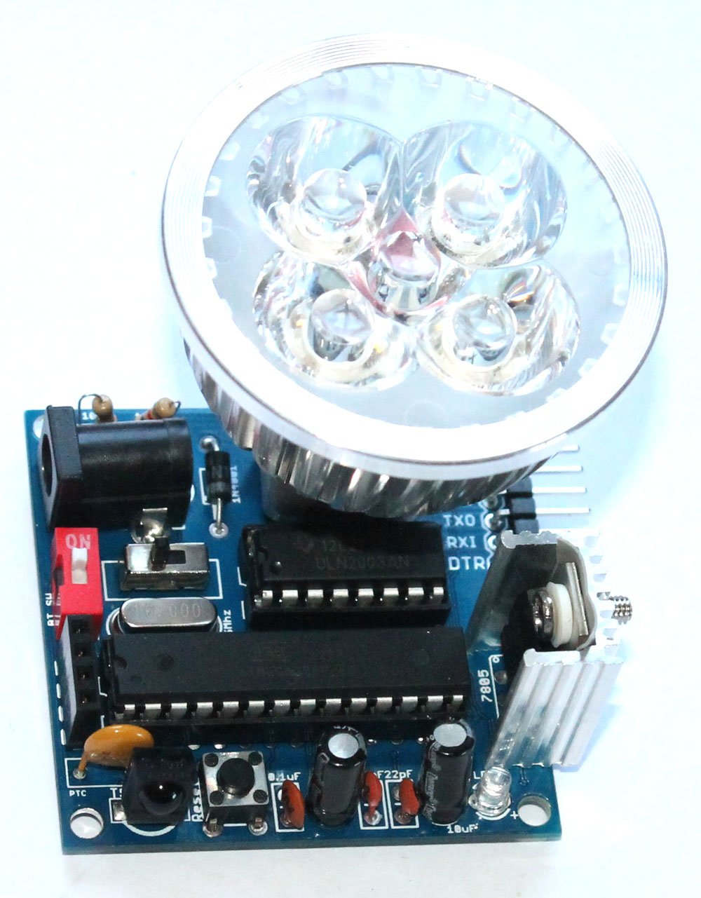
Amarino lamp is fully programmable. The kit package consists of FTDI basic breakout board, you can use it to program the lamp. The lamp is based on Arduino.

Connect the FTDI basic breakout board to the lamp, open the Arduino programming interface and upload your sketch.

REMEMBER: Turn off the red colored 1P DIP switch 1-position-2p-side-style-dip-switch-redwhile uploading sketch(if the Bluetooth module has been stacked over the 4 pin female header)

programming

Documents: 

  1. About Amarino Lamp
  2. Assembly Tutorial
  3. Amarino Lamp- Light sensor
  4. Lamp test with different phone sensors
  5. How to program Amarino lamp

Where can you buy ?

buildcircuit    etsy

Assembly guide- DIY Arduino

We are now selling the BLUE COLORED DIY Arduino kit

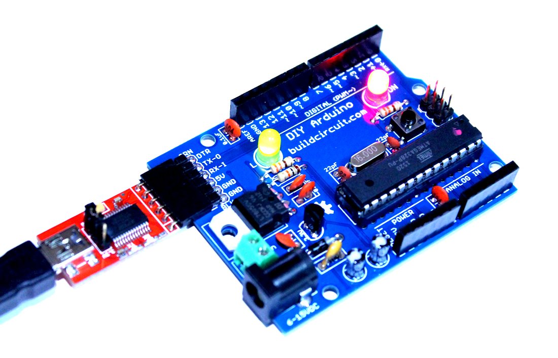
This post shows you how to assemble the DIY Arduino board.

DIY Arduino Kit for Beginners (8)

The assembly process is straight forward. It can be easily assembled if you follow the silkscreen indicators(labels) and have beginning experience with a soldering iron. You will need to read the resistor bands or use a multimeter to determine the resistor sizes.

Note: You will need either an FTDI Basic or FTDI cable to load code using the Arduino IDE.

Kit Includes:

  • 1 x Arduino-Compatible plated through holes (PTH) Kit PCB
  • 1 x ATMega328 with Optiboot bootloader
  • 1 x L78L33 3.3V Voltage Regulator
  • 1 x 5mm Green LED
  • 1 x 5mm Red LED
  • 2 x 330Ohm Resistor
  • 1 x 10kOhm Resistor
  • 1 x 16MHz Crystal
  • 2 x 22pF Ceramic Capacitors
  • 5 x 0.1uF Ceramic Capacitors
  • 2 x 10uF Electrolytic Capacitors
  • 1 x LM7805 5V Regulator
  • 1 x Diode 1N4001
  • 1 x Resettable Fuse PTC (300mA)
  • 1 x 28-Pin DIP Socket (To seat your ATMega)
  • 1 x Push Button Reset Switch
  • 2 x 6-Pin Female Headers
  • 2 x 8-Pin Female Headers
  • 1 x 6-Pin Right Angle Header (To connect your FTDI Basic)
  • 1 x 0.1uF Capacitor
  • 1 x DC Barrel Jack
  • 1 x 2-pin screw terminal
  • 1 x 6 pin ICSP header

Description of this DIY Arduino board is available on this page.

Assembly video: 

See all the assembly images on Flickr

You can see all the assembly steps on this post.

Step 1: Start with the resistors 10K(Brown-Black-Orange) and 2 pcs 330R (Orange-Orange-Brown).

1 Fix all the resistors

You can see all the assembly steps on this post.

Step 2: Then fix the 16Mhz crystal oscillator, 1N4001 diode and 2pcs of 22pF capacitors.

4- Fix 22pF capacitor

You can see all the assembly steps on this post.

Step 3: Fix 5 pcs of 0.1uF capacitor. The image shows only 4pcs. I actually forgot to solder the last one, which is right after the Vin point.

5- 4pcs of 0.1uF capacitor-another angle

capacitor

The left over(remaining) 0.1uF capacitor

Step 4: Solder LM7805 voltage regulator, 3.3V regulator and the tactile switch.

8- fix 3.3V regulator

You can see all the assembly steps on this post.

Step 5: Now fix the PTC resettable fuse (300mA), 28pin IC header, 2 pin screw terminal and 2pcs of 5mm LEDs.

11- Fix 28 pin IC header and the LEDs

You can see all the assembly steps on this post.

Step 6: Fix the DC barrel, 2 pcs 10uF capacitors, 6 pin male header (for connecting FTDI basic module) and ICSP header.

17- close up

Step 7: Finally, fix the stackable headers and Arduino UNO chip. Your Arduino is now ready.

19- The DIY arduino is now ready

You would need a FTDI basic module to program the Arduino board. The following image shows how to connect the FTDI basic module.

21- FTDI connection to Arduino and computer

You can see all the assembly steps on this post.

See all the assembly images on Flickr

See the output below:


You can purchase this kit from here:

BC-2138

Do-It-Yourself (DIY) Arduino- Make Your Own Arduino

US $14.95
This kit contains everything you need to build

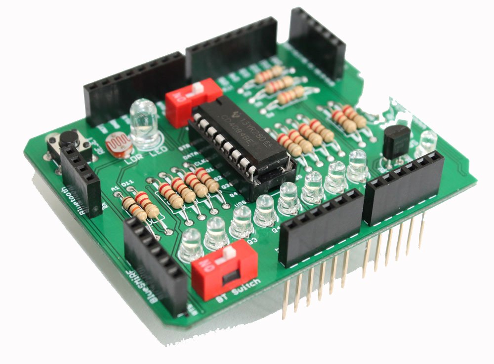
Assembly instructions for Amarino 3.0 DIY shield

Step 13- Solder stackable header

This post gives you the idea for assembling the Amarino shield. To get full details about this shield,  CLICK HERE.  When you buy the kit package, you will get the following PCB. The PCB clearly shows the pin and component names, so, it should help you to get idea of connections of components to Arduino.  For example, LDR is connected to A1 and RGB LED is connected is to D3, D5 and D6 and you can see those pins labeled on the PCB. (more…)

How to assemble Magician Chassis

Check out similar robotics chassis at Buildcircuit store

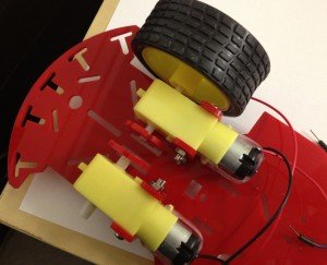
Sparkfun.com has recently released a simple, easy and useful robot platform for robotics amateurs. It is called “Magician Chassis”. You can use the chassis for different kinds of robots, for example, line sensing, obstacle detecting and smart phone controlled robots. I have recently published an easy project about smart phone controlled robot. I have also used Magician Chassis on my project. I recommend this chassis for robotics amateurs and novices because it is cheaper than other products I have known. You can use it for learning and experimenting the basics of robotics.

(more…)

Search for products

Back to Top
Product has been added to your cart