DIY KIT 66- Basic electronic dice with 7 LEDs

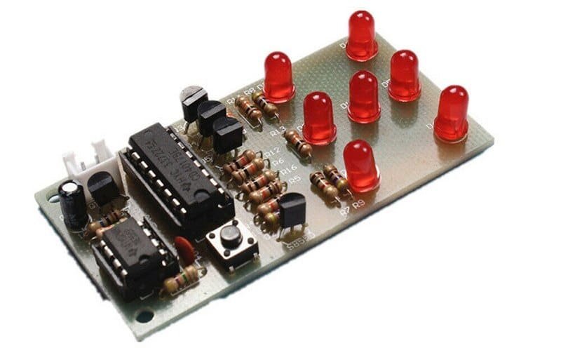
This is yet another CD4017 and NE555 based digital dice with 7 LEDs. When you press the tactile switch, the LEDs start flashing and stop with a pattern that represents a number between 1 to 6 like real dice. The display will always random.

[ytvg_container layout_img_size=”maxres” popup_ads_enabled=”true” main_font_weight=”” heading_font_weight=”” meta_font_weight=”” data=”%5B%7B%22name%22%3A%22Kit%20assembly%20video%20tutorial%22%2C%22urls%22%3A%22https%3A%2F%2Fyoutu.be%2FcxRttGrZW0c%22%7D%5D” popup_width=”1200px” popup_ads_google_ads_client_id=”ca-pub-3959191968523970″ popup_ads_google_ads_slot_id=”7854790433″ text_color=”#000000″ main_font=”Raleway” main_color=”#000000″ title_color=”#000000″ popup_link_color=”#ee1133″ main_font_size=”16px” main_font_line_height=”20px” heading_font_size=”20px”]

DIY KIT 61- Digital clock DIY kit with thermistor and photoresistor

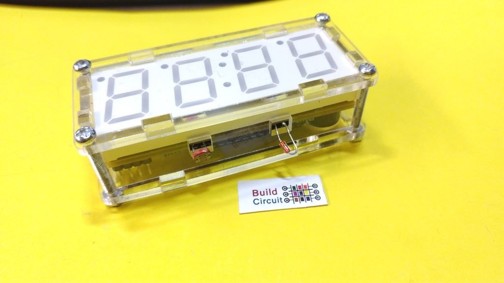
This is yet another digital clock DIY kit for electronics beginners. I have previously published several posts related to the digital clock. This kit is no different from those kits, it also displays time and the additional functions and temperature display and alarm. It also has a photoresistor which makes it sensitive to ambient light, the clock will automatically be brighter during the day than at night. The display is 0.8 inches big. With a transparent case, components can be well protected and the clock looks stylish. It is a perfect kit for electronic DIY enthusiasts, school training lessons, etc. (more…)

DIY KIT 60- Digital clock kit-II

This digital clock kit looks very much similar to this kit, the kit is actually slightly advanced than the previous kit. It has enough functionalities like any other regular clock. It is very accurate. It is an easy to build kit and perfect to start to develop your soldering skills. It uses the chip AT89C2051. (more…)

DIY KIT 49- Dark sensor

This is yet another dark sensor DIY kit. It is slightly different from other dark sensor kits. It has a buzzer and a photodiode that makes it different from other kits. Along with the LED, the kit turns on the buzzer whenever it senses darkness.

See all the images below to get the idea for assembly. You can see all the images on Flickr also.

This is yet another dark sensor circuit

One more dark sensor project

DIY KIT 20- How to make a simple multivibrator

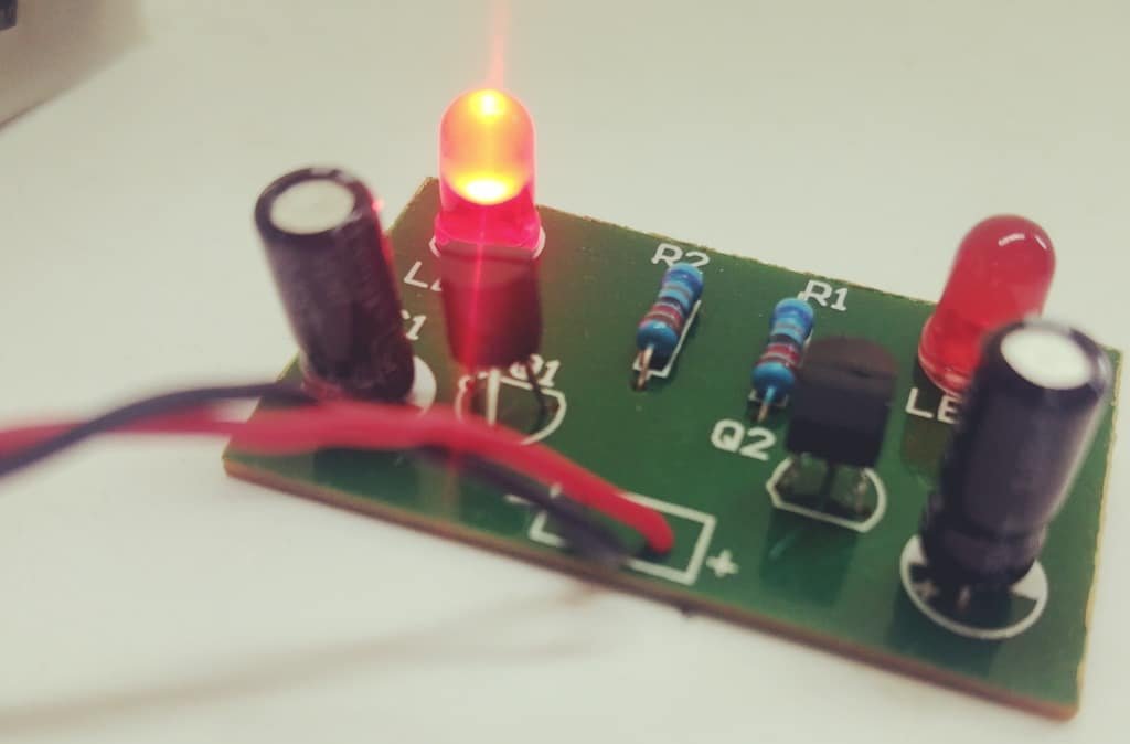
This is a simple multivibrator kit using two transistors(S9014), two capacitors, and a few other components. The working principle of a multivibrator has been explained in previous posts also. You can read about the multivibrator circuit on this page.

The two LEDs on the PCB flash alternately, that’s all you see on the circuit board. It is a very basic electronic kit for electronics beginners. (more…)

DIY KIT 19- Remote Operated Musical Bell DIY Kit

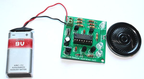
Remote operated musical bell is one of the interesting experiments every electronics hobbyist would like to make. We have made a very simple remote-operated musical bell DIY kit that requires your half an hour labor to make it work. It uses CD4017 decade counter, UM66 or BT66 musical chip and TSOP4838 infrared sensor as its important components. (more…)

DIY KIT 17- DIY ZIF Arduino programmer

It is just another ‘build your own Arduino’ project. BuildCircuit has worked on similar projects before. The most popular project is a DIY Arduino kit. The DIY Arduino looks similar to the real Arduino boards and uses an FTDI basic programmer to program the chips.

The kit that we are going to work on this article is also a DIY Arduino. It comes with a zero insertion force (ZIF) IC socket. You can simply insert an Arduino chip and program it. The board has a header to connect an FTDI basic module that can be used to program the Arduino chip.

(more…)

DIY KIT 12- Hee-Haw Siren With Flashing LED

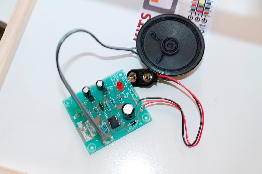
This video shows all the steps to build the HEE-HAW Siren Project from Jaycar. The kit is based on NE555 IC. The timer NE555 IC is configured in astable mode.

You will hear a hee-haw siren similar to an ambulance and you will see the two green and red flashing LEDs.

The kit is very much similar to BuildCircuit’s project: https://www.buildcircuit.com/light-activated-police-siren-using-555-timer-and-light-dependent-resistorldr/ This kit is good for electronics beginners and extremely easy to build.

Watch the video to see all the assembly steps:

See all the images below to get ideas for assembly:

Download Jaycar’s Short Circuits Volume 1, 2 and 3:

Volume 1: https://www.buildcircuit.com/wp-content/uploads/2020/11/Short-Circuits-Volume-1.pdf

Volume 2: https://www.buildcircuit.com/wp-content/uploads/2020/11/Short-Circuits-Volume-2.pdf

Volume 3: https://www.buildcircuit.com/wp-content/uploads/2020/11/Short-Circuits-Volume-3.pdf

The simplest and the cheapest FM transmitter- Do-it-yourself(DIY) kit for amateurs

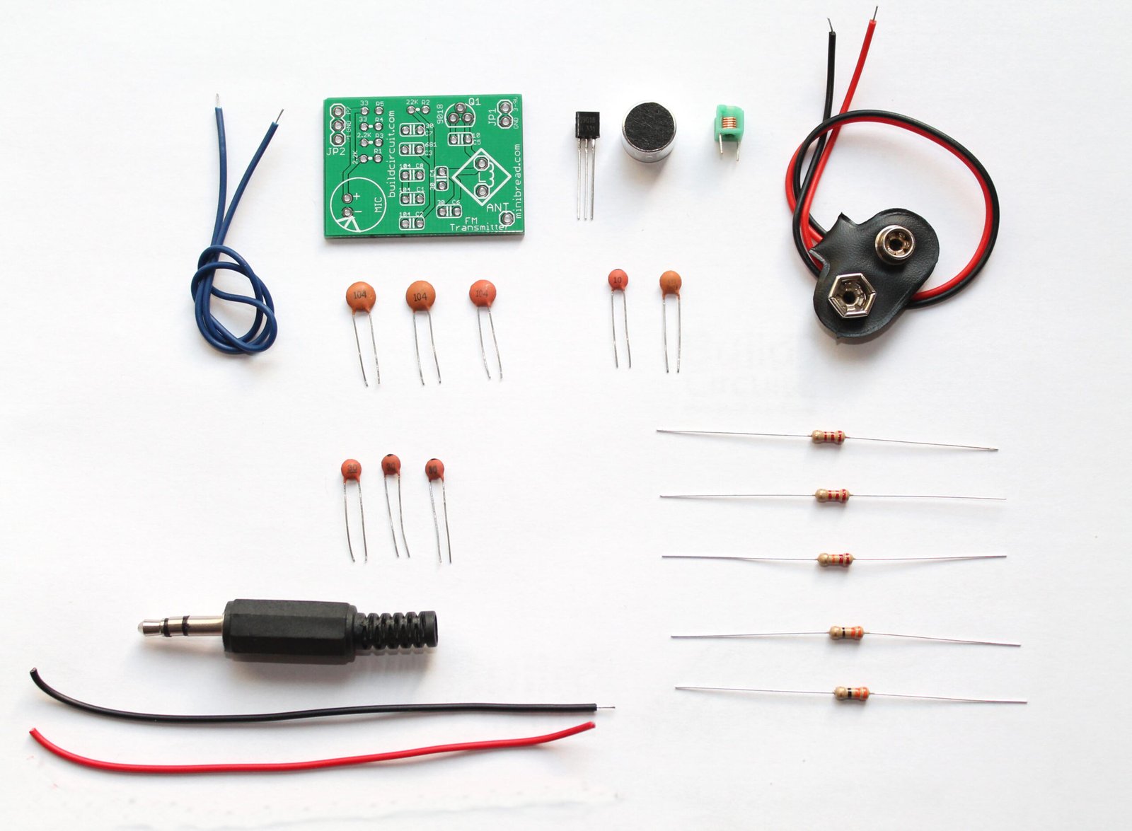
Here’s one of the easiest, simplest and the most popular FM transmitter for amateurs and electronics beginners. With this DIY kit, you can transmit your voice or audio over an ordinary FM radio within the FM broadcast band. It is a DIY kit designed by Sagar Sapkota. You can buy this kit from BuildCircuit Store. The best thing about this transmitter is that you don’t have to make your own inductor for this kit. Making an inductor is bit hard for amateurs. Besides, this kit is not only capable of transmitting voice using microphone but also transmitting music from your music player. (more…)

Digital object counter DIY kit

We are now selling CD4026 and CD4029 up and down counter modules.

This kit is based on my previous tutorial on ‘digital object counter‘. I had published the tutorial under ‘minibread’ category. Please check the tutorial. 

IMG_0673

Digital object counter

In that tutorial, you can see that there is only one seven segment display and there is no reset switch. Well, that was extremely basic circuit.

What’s new?

Digital object counter

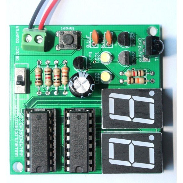
My new DIY digital object counter works with TSOP4838 infrared receiver   and there are two seven segment displays displaying numbers from 0 to 99.   An IR transmitter is oriented towards the TSOP4838 infrared receiver of counter module and objects are moved between the counter and transmitter modules. Each time an object passes between the two modules, the seven segment displays show increment in numbers. The counter module can be reset to 0 at any time and restart the counting.

Watch the video below:

The counter can be reset to 0 by pressing the reset switch(see on video). The counter stops counting if the IR rays is continuously falling on the IR sensor. As soon as an object obstructs the IR signal, the counter immediately counts the interruption.

The distance between the counter module and the IR transmitter should be around 1 meter.

The module can also be tested with general remote control. Thus, you can also call it as a simple remote tester. For each press on your remote control, there is increment in number.

Power supply: The counter works with a 9V battery and the IR transmitter works from 6V to 9V.

Counter operating with a remote control:

Schematic of counter module:

Counter

When TSOP4838 infrared receiver receives infrared signal, it triggers BC557 and switches on LED2. This trigger also charges the RC circuit network made up of C1(100uF), R3(1K) and R4(1K) and switches on the transistor BC547 for a few seconds. Transistor Q1 switches on the LED1 and gives clock signal to IC1(CD4026). For each clock, CD4026 drives the seven segment display and increases the numbers on the display.

Pin number 5 of IC1 is connected to pin 1 of IC2 for chaining the two CD4026 chips. For adding one more digit, the pin 5 of IC2 should be connected to pin 1 of IC3.

Schematic of IR transmitter module:

IR transmitter schematic

GO TO IR TRANSMITTER ASSEMBLY INSTRUCTIONS PAGE

IR transmitter is based on astable mode of 555 timer. The 555 timer, resistors and capacitor on the transmitter module output IR rays at 37.974Khz(approximately 38Khz). The TSOP4838 infrared module operates at 38KHz infrared frequency, however, that is not so strict with these kinds of basic experiments. It actually operates at frequencies between 30Khz to 40Khz.

Use astable mode frequency calculator for finding out the frequency of 555 timer. While using the online calculator, enter R1=18K, R2=10K and C1= 0.001uF, you will get 37.974 KHz.

How to use the kit

Place the two kits facing each other in a straight line. The IR receiver(on the counter module) and the IR LED(on the transmitter module) can be kept in a line of sight(straight line). When you move an object in between the two kits, the counter module counts the number of interruptions in the line of sight.

Behavior 1: When you place the IR receiver and the IR LED in a straight line, the two 3mm LEDs on the counter module are switched on and it counts as soon as there is an object in the line of sight.

Object counter

Behavior 2: When you place the IR receiver and the IR LED close to each other but not in a straight line, the two 3mm LEDs on the counter module are switched off and the counter counts as soon as an object moves away from the line of sight.

Slide2

Please watch the following video to be more clear:

Other related tutorials:


BC-3014A

3 Digit Digital Objects Counter With Laser Module

US $14.95US $19.95
This is 3 digits digital object counter kit

Check out all the counters

COU-18

1.8" Photoresistor And Laser Operated Medium Digital Objects Counter

US $24.95
This is an upgraded version of the previous
SCO-23

2.3" Common Anode Seven Segment Display Driver

US $19.95
COU-902

2.3" common cathode seven segment display driver

US $14.95US $19.95
This is a CD4026 based up counter driver

CD4026- 1 Digit Up Counter Module

US $4.95
  • It works as an UP counter. You can
Sold out
COU-23

Photoresistor And Laser Operated Large Digital Objects Counter With 2.3" Displays

US $29.95
A laser light module illuminates the photoresistor continuously

Amarino Nano 1.0

Amarino Nano 1.0

amarino nano

[mpc_vc_quote quote=”Amarino Nano 1.0 kit facilitates communication between Arduino Nano and Android applications via Bluetooth. “]

Amarino Nano Output

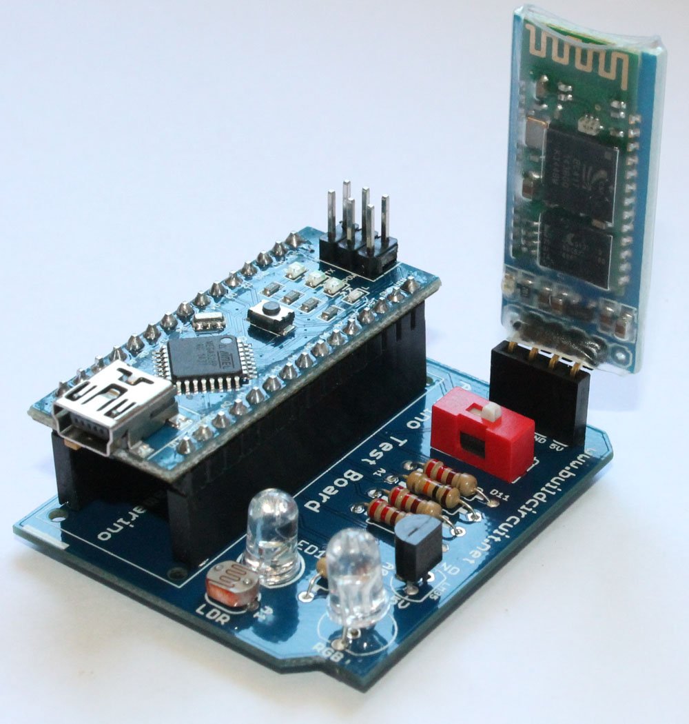
Amarino Nano is a very simple kit for experimenting with Amarino toolkit– a quick prototyping application based on Android. However, you don’t essentially need Amarino toolkit to experiment with this kit.

It works with many other apps made for Android-Arduino communication via Bluetooth. You can also use this as a simple shield for Arduino Nano.

Amarino Nano is based on: 

  1. Arduino Nano– You need an Arduino Nano for Amarino experiments.
  2. Amarino toolkit application: Amarino toolkit is an Android application. Read more…

amarino app

3. Bluetooth communication medium: You will need a Bluetooth adapter module to make communication between Arduino Nano and Amarino toolkit.

What can Amarino Nano do: 

Like any other Amarino kits (Amarino DIY shield, Amarino evaluation shield), Amarino Nano 1.0 basically facilitates interaction between Arduino and Android via Bluetooth communication medium.

Features: 

  1. Control RGB LED: You can control an RGB LED from your Amarino application. In this experiment, you transmit control signals from Android to Arduino. Watch this video. See all the steps.
  2. Display LDR sensor data on Sensor Graph: You can see light sensor data and a simple graph on your Android phone interface. The sensor data is transmitted from Amarino Nano 1.0 kit to the phone. In this experiment, you transmit sensor signals to your Arduino and vice versa. Watch this video
  3. Display temperature sensor data on phone: You can see temperature sensor data (from LM35) on your Amarino application interface. In this experiment too, you transmit temperature sensor signals to your Arduino and vice versa. Watch this video.
  4. Control 5mm LED : You can control a 5mm white LED present on the kit. You can simultaneously control the LED and see sensor data. In this experiment, you transmit and receive signals from Android to Arduino and vice versa simultaneously. You can see in the experiment no.3.
  5. Use as Arduino Nano Shield: You can use this kit to experiment with Arduino Nano. You don’t need any Android app for that 🙂 .
  6. Test any Android app for Arduino: You can test any Android App made for Android-Arduino communication via Bluetooth. You can find several apps on Google Play.
[mpc_vc_deco_header type=”h6″ align=”left” text=”What does the kit package include”]

Amarino Nano 1.0 Assembled: 

Amarino Nano 1.0 “assembled version” has all the components assembled on the PCB board. In addition to the circuit board, you will get the following:

1. Bluetooth adapter module

2. Arduino Nano 1.0 (Chinese version with CH340G chipwith mini USB cable

Amarino Nano 1.0

Amarino Nano 1.0 DIY kit:

Amarino Nano 1.0 comes with all the components required to build the kit. With basic soldering knowledge you can easily build the kit.

You will get the following components:

  1. 1 x PCB- Click on the link to see how the PCB looks. You will get all the direction for soldering by seeing on the PCB. It’s very easy.
  2. 4 x 220 Ohm resistors: These resistors are current limiters for RGB and 5mm white LEDs.
  3. 1 x 10K Ohm resistor: This resistor is connected to LDR (photo resistor, light sensor) forming a voltage divider network.
  4. 1 x Light dependent resistor(LDR)/ Photoresistor: This sensor is used for sensor graph experiment.
  5. 1 x LM35 temperature sensor: This temperature sensor is used for transmitting temperature data to the Amarino application.
  6. 1 x 1P DIP switch: This switch is used for switching on/off the Bluetooth module while programming the Arduino Nano. It is not a power on/off switch.
  7. 1 x 5mm LED
  8. 1 x RGB LED: This is used for RGB lamp experiment. You can control the LED with RGB Amarino application.
  9. 1 x 4 pin female header: This header is used for stacking the Bluetooth adapter module.
  10. 2 x 15 pin female headers: These headers are used for stacking the Amarino Nano.
  11. 1 x Arduino Nano with USB cable: You will get a Chinese version of Arduino Nano with a mini USB cable. It has CH340G chip.
  12. 1 x Bluetooth adapter module: This Bluetooth module facilitates communication between Arduino Nano and Amarino kit.

amarino nano

How to assemble the DIY version of Amarino Nano 1.0: 

  1. You can get the assembly tutorial on this page.
  2. You can see all the image on Flickr and get soldering idea.

Applications and Libraries

Before you begin your experiments with Amarino Nano 1.0, you need to download the following:

amarino app

  • Download Amarino Library for Arduino and move it to the Libraries folder. You can check here if the Amarino team has upgraded the library. It’s always good to use the updated version :) .  If the link does not work, you can download the library from this link. 
  • Other applications:

a. RGB LED Control application This application is for controlling the RGB LED.

multicolor lamp

If you need the source code, download it from here. The source code is optional and useful only for Android programmers. If the link does not work, download it from here.

b. Sensor graph application: This application is for getting LDR sensor signals from Arduino board. Source code for this application can be downloaded from here.

sensor graph

c. LM35 temperature sensor application:  With this application, you can transmit LM35 temperature sensor data to your Amarino application.

temperature sensor

Source code for this application can be downloaded from here.

Experiments:

As you can see from the schematic, the pins of Arduino Nano which are connected to the sensors and other components:

Analog Pins: 

A1: Connected to Photoresistor

A0: Connected to LM35DZ temperature sensor

Digital pins:

RGB LED: D3: Red, D5: Blue, D7: Green.

D11: 5mm White LEDAmarino Nano1

1. RGB LED Control experiment: In this experiment, you control the RGB LED with the RGB multicolor lamp application.

2. Sensor Graph: In this experiment, you can fetch the light sensor data on your Amarino interface. The Arduino sends sensor data to your phone.

3. Temperature sensor data on your phone: In this experiment, you can fetch the Lm35 temperature sensor data on your Amarino application interface. The Arduino sends sensor data to your phone and your phone can control the 5mm LED present on the Amarino Nano kit.

Where can you buy this kit ?

The kit is available at BuildCircuit Store (www.buildcircuit.com.au- Free Shipping in Australia)

Amarino Nano-1-1Buy now button

Cosmarino Assembly Tutorial

If you have come to this page from a search engine, please check this page first, you will eventually come to this page again.

About Cosmarino

The assembly process of the Cosmarino kit is very straight forward. You just need to follow the silkscreen labels to get the idea of assembly. A basic knowledge in soldering is enough for assembling the kit.

To be quick, you can see all the assembly images on Flickr. 

Step 1: Solder all the 220 ohm resistors

Step 1- Solder 220 Ohm resistors

Step 2: Solder 330 Ohm and 10K ohm resistors

Step 2- SOlder 330 Ohm and 10K Ohm resistors

Step 3: Solder 1N4001 diode.

Step 3- Solder 1N4001 Diode

Step 4: Solder LDR/ photoresistor.
Step 4- Solder LDR

Step 5: Solder BD139 NPN transistor
Step 5- Solder BD139 NPN transistor

Step 6: Solder LM35DZ temperature sensor
Step 6- Solder LM35 temperature sensor
Step 6.1- LM35 temperature sensor

Step 7: Solder TSOP4838 infrared sensor
Step 7- Solder TSOP4838 infrared sensor

Step 8: Solder 1P DIP switch
Step 8- Solder 1P DIP switch

Step 9: Solder 5mm white LED
Step 9- Solder 5mm White LED

Step 10: Solder RGB LED
Step 10- Solder common cathode RGB LED
Step 10.1- RGB Common cathode LED

Step 11: Solder 2pcs 15 pin female header
Step 11- Solder 4 pin and 15 pin female headers

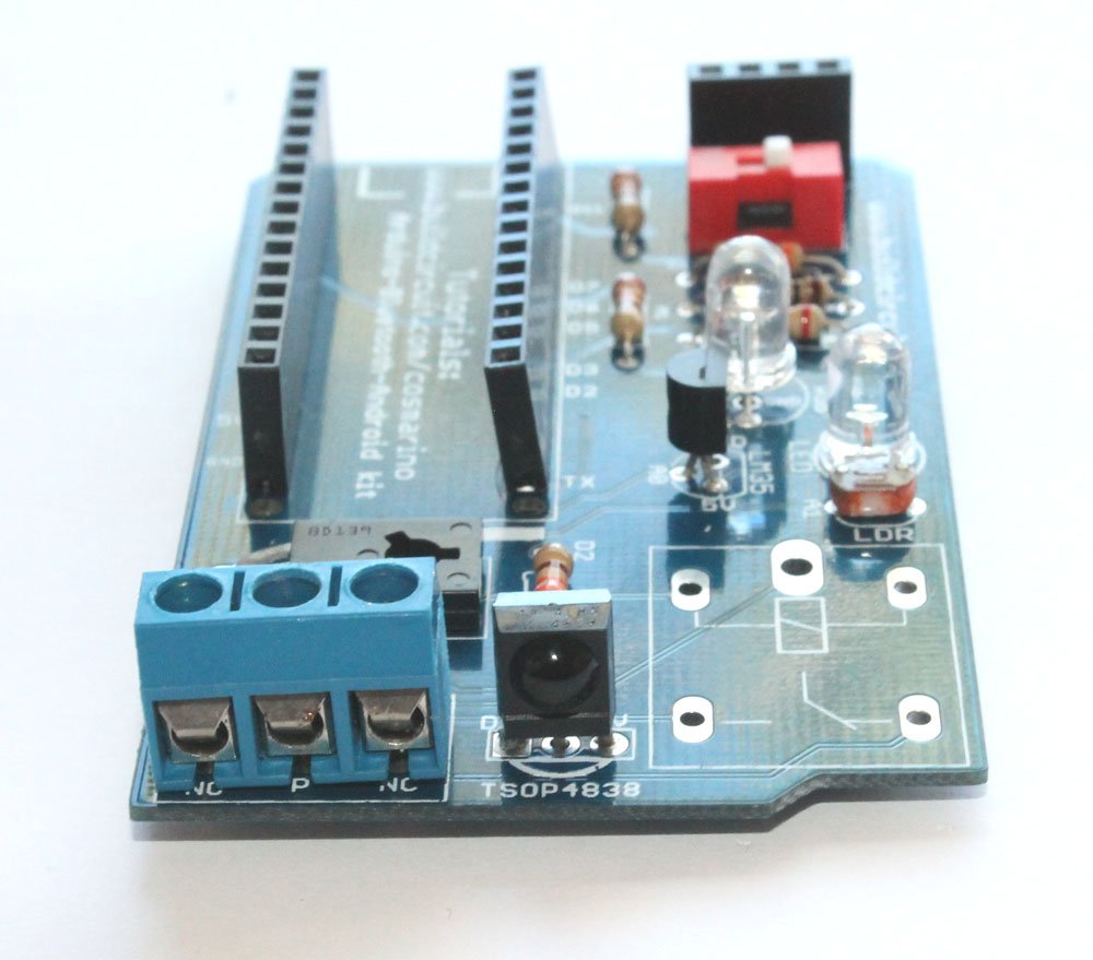
Step 12: Solder 3 pin screw terminal
Step 12- Solder 3 pin screw terminal
Step 12.1- 3 pin screw terminal

Step 13: Solder 5V relay
Step 13- Solder 5V relay

Step 14: Stack Bluetooth module and Arduino Nano
Step 14- Stack Bluetooth module and Arduino Nano

The kit is ready to use
Step 15- Use Mini USB cable to program Arduino Nano - Copy


Cosmarino Experiments


Related documents:

Where can you buy ?

buildcircuit   ebay   etsy

Cosmarino Experiments

If you have come to this page from a search engine, please visit this page first, you will eventually come back to this page again.

About Cosmarino 

Cosmarino is a versatile kit that facilitates communication between Android and Arduino in a simple way.

We can do several experiments with this kit. In this tutorial we have shown experiments related to Amarino only. However, you can test the kit with several other Android app available at Google Play.

Before you start the experiments, please know how the components are connected to the Arduino Nano.

1. OUTPUT- RGB LED: R= D3, Blue= D5 and Green= D6. All these digital pins have Pulse Width Modulation fuctionality.

2. OUTPUT- 5mm LED: Digital pin D11

3. OUTPUT- 5V relay= Digital pin D2

4. INPUT- LDR/Photoresistor= Analog pin A1

5. INPUT- LM35 temperature sensor: Analog pin A0

6. INPUT- TSOP4838 infrared sensor= Digital pin D7

Steps for Amarino experiments: 

Amarino_logo-W490

For all the experiments, you have the following things in common:

Step 1: Amarino Toolkit MAIN application: This is the main Amarino toolkit application to be installed on your Android phone. There are other applications which work only after installing the main application. If the link does not work, download the application from here.

amarino main app

Amarino Nano (1)

Step 2: Amarino Library for Arduino: Download it and move it to the Libraries folder. You can check here if the Amarino team has upgraded the library. It’s always good to use the updated version .

If the given link does not work, you can download the library from this link. 

meet android

Step 3: Connect the Bluetooth module to the circuit board. Please note how the Bluetooth module has been stacked over the 4 pin female header. After you stack it on the circuit board, you will see a red LED blinks on the Bluetooth module.

bluetooth module  Bluetooth module

Step 14- Stack Bluetooth module and Arduino NanoNote how the Bluetooth module has been stacked over the board.

Then, activate the Bluetooth function of your phone.

Amarino Nano (2)

Step 5: After you see an LED blinking on the Bluetooth module, open the Amarino Main application, you see the following interface:

Amarino Nano (1)

On the Amarino main application interface, touch Add BT Device. That will display the Bluetooth module close to your Android phone.

Amarino Interface

Select the linvor Bluetooth module. Remember to note down the MAC ID also. In this example, the MAC ID is 20:13:05:09:15:39. It is unique for all the modules. You will need this MAC ID in the next step. Note that the MAC ID is unique for all modules. It is never same for any two Bluetooth modules.

Pressing the “Connect” button display a text box(for the first time), where you need to enter the pairing code, which is 1234. This connects the application to the chosen adapter. You can connect only one adapter at one time.

Pairing code: 1234

Once the adapter is paired up, you don’t need to pair it again. 

Now we can move to the experiments below:

 Experiment 1- RGB LED Control: 

RGB LED is connected to digital pins 3(RED), 5(GREEN) and 6(BLUE).

  • Download the RGB LED control application and install it on your phone.
  • Download the Arduino source code and upload it to your Arduino Nano. NOTE: You need to switch off the 1P DIP switch while uploading the sketch. After uploading switch it on again.
  • Set Bluetooth MAC ID. It is different for all Bluetooth modules. For example, my Bluetooth module has MAC ID: 98:D3:31:70:3A:98, so, I used that. No two Bluetooth modules can have the same MAC ID. You will have a different MAC ID for your module. Enter the MAC ID that you had noted down in the previous step.

RGB control application

  • As soon as you open the application, the app will connect to the Bluetooth module and you can simply control your RGB LED. As you move the slider, the color on the RGB LED changes. Remember to switch on the 1P DIP switch, otherwise, it won’t work. 

The multicolor lamp application

RGB LED control using “Arduino Bluetooth RGB LEDs” android App:

Cosmarino app

There are several Android applications that can control Amarino Nano kit. Here’s one application that we have tested:

You can then simply connect Bluetooth of your phone to the external Bluetooth module and control the Amarino Nano kit.

Experiment 2: Sensor Graph display

The photoresistor/LDR is connected to A1 and the 5mm white LED is connected to D11.

  • Download the sensor graph application and install it on your phone.
  • Download the Arduino source code and upload it to your Arduino Nano. NOTE: You need to switch off the 1P DIP switch while uploading the sketch. After uploading switch it on again.
  • Set Bluetooth MAC ID. It is different for all Bluetooth modules. For example, my Bluetooth module has MAC ID: 98:D3:31:70:3A:98, so, I used that. You will have a different MAC ID for your module.

Sensor Graph

  • Open the application and see the sensor data on your phone. You may also control the 5mm LED simultaneously. Remember to switch on the 1P DIP switch, otherwise, it won’t work. 

sensor graph (2)

Experiment 3: LM35 temperature sensor data display

  • Download the LM35 temperature senor display application and install it on your phone.
  • Download the Arduino source code and upload it to your Arduino Nano. NOTE: You need to switch off the 1P DIP switch while uploading the sketch. After uploading switch it on again.
  • Set Bluetooth MAC ID. It is different for all Bluetooth modules. For example, my Bluetooth module has MAC ID: 98:D3:31:70:3A:98, so, I used that. You will have a different MAC ID for your module.

temperature sensor log in

  • Open the application and see the sensor data on your phone. You may also control the 5mm LED simultaneously. Remember to switch on the 1P DIP switch, otherwise, it won’t work. 

LED control app interface

Relay control

There is a 5V relay on the Cosmarino kit. You can control the relay using your phone application or a normal infrared remote control.

Control the relay using general Android application and Infrared remote control

There are hundreds of applications on Google Play that have been made for Arduino and Android application. You can pick up any of those apps and control the kit.

In this example, we have picked up this application which transmits text ‘h’ every time the green button is pressed. We have programmed it in such a way that the relay is switched on if the Arduino gets an ‘h’.

TIP: If you want to know what text a random Android app sends to Arduino, you can check out this tutorial. The tutorial shows you what Arduino receives from the phone and what Arduino sends to the phone. See this video also.

The kit is fully programmable. Please remember to switch off the red DIP Bluetooth switch while programming, otherwise, the Arduino Nano cannot be programmed. You should switch it back again after the kit has been programmed.

Step 1: Install this Android application from Google Play.

external app

Step 2: Upload any of these sketches:

If you intend to control the relay with infrared remote control, then, you need to download the library and copy it to the libraries folder of Arduino.

Download Infrared sensor library from the original link 

Step 3: Open the Android application and search for the Bluetooth module stacked on the circuit board. Pair up the module with your Android application(to be done only once). Pairing code= 1234. You need to pair up with the module only once.

Step 4: Switch on/off the relay with the application. You can simultaneously control the lamp with your infrared remote control also if you have uploaded this sketch.

Related documents:

Where can you buy ?

buildcircuit   ebay   etsy

Amarino LED Lamp

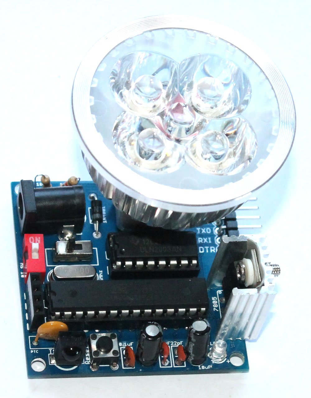
Amarino Lamp is a versatile programmable LED lamp based on Arduino. The lamp has an inbuilt Arduino as its controller. PWM signals from Arduino are fed into UNL2003A and this chip controls the LED lamp. You can also simultaneously control the lamp with an infrared remote control. It has the following features:

  • Android app controlled: The LED lamp can be controlled with several Android applications made for controlling Arduino or communicating with Arduino via Bluetooth. We have tested the kit with Amarino toolkit and many other Android applications.
  • Bluetooth support: The control signals from Android phone are sent to the lamp via Bluetooth. There is a Bluetooth module connected to the circuit board that facilitates communication between Android and Arduino.
  • TSOP4838 infrared sensor: There is a TSOP4838 infrared sensor on the circuit board which allows you to control the lamp with any kind of TV/DVD remote control.
  • Fully programmable: The lamp is fully programmable because it has an inbuilt Arduino. You will need an FTDI breakout board to program the chip on the board. The kit package includes the FTDI basic breakout board.
  • Resettable PTC fuse: The lamp has a resettable PTC fuse which protects the circuit board from over current flow. In this kit, if the circuit tries to draw more than 500mA of current (if you have a bad short for instance) the PTC would ‘trip’ (by heating up). The increased resistance (trip state) would break the circuit and allow only a small leakage current.

Specification of lamp(according to the manufacturer): This is not the specification of whole circuit.

lamp image

MR16 4W LED Lamp
Lamp base MR16
Power 4W
Voltage 12V AC/DC
Lumens 400-500LM
Beam angle 45°
Dimension diameter 48mm x 61mm high
Weight 37g
Life time more than 50000 hours
Color temperature Cool white:5700-6300K

The kit package includes:

android lamp- main-small

The kit package includes everything that you need to build the LED lamp. On the assembly tutorial page you will get the list of components.

“The kit package does not include 12V/500mA power supply. You need to buy it separately”.

A 12V power supply with 500mA or 1A output is enough for this lamp.

You can buy similar to this one: 12V DC Power Adapter Supply 2.1mm 1A, CCTV

We do not sell that because different countries have different plug standards, so, we cannot stock that for all countries, not even Australia.

List of components is available on the assembly tutorial page.

About ULN2003:

Download datasheet

The ULN2003A is a high-voltage high-current darlington transistor array. The chip consists of seven npn darlington pairs that feature high-voltage outputs with common cathode clamp diodes for switching inductive loads. The collector-current rating of a single darlington pair is 500mA.

Because ULN2003 can drive 500mA, we chose MR16 4W LED lamp that can be driven easily by ULN2003A.

Schematic:

Smart phone lamp

How does it work ?

“You can simultaneously use Android phone application and IR remote control to operate the LED lamp.”

Bluetooth mode: 

The Bluetooth module on the kit is paired up with the Bluetooth of phone and control commands are sent from the phone application. The commands are interpreted by the Arduino UNO microcontroller and ULN2003 is driven to operate the LED lamp.

Infrared mode:

Infrared signals are sent from the infrared remote control and those signals are interpreted by Arduino UNO chip and control commands are sent to the ULN2003 to drive the LED lamp.

Using Amarino toolkit application

You can try several Amarino related experiments with this lamp.

Amarino_logo-W490

Step 1: Download Amarino main application from Amarino website(www.amarino-toolkit.net) and install it on your Android phone. Optional link (use this if the previous link does not work)

amarino main app

Step 2:  Download Meet Android Library and copy it to the Libraries folder of Arduino. Optional link

meet android

Step 3: Upload this sketch to the Atmega328P-PU Arduino UNO chip that’s on the circuit board. You will also need a library for remote control function, download the library and copy it to the libraries folder of Arduino.

Download Infrared sensor library from the original link 

Step 4: Connect the Bluetooth module to the circuit board. Please note how the Bluetooth module has been stacked over the 4 pin female header. And remember to SWITCH ON the circuit board. After you switch on the circuit board, you will see a red LED blinks on the Bluetooth module. Use a 12V (500mA/1A) power supply to power up the lamp.

bluetooth module  REMEMBER: Switch ON the 1P DIP RED color switch also. This switch:1-position-2p-side-style-dip-switch-red. Turning it on makes connection between the Bluetooth module and the microcontroller. But, this switch should be turned off while uploading a sketch.

Step 18- Fix a Bluetooth module over the 4 pin female headerSee how the  Bluetooth module has been stacked.

Then, activate the Bluetooth function of your phone

Amarino Nano (2)

Step 5: After you see an LED blinking on the Bluetooth module, open the Amarino Main application, you see the following interface:

Amarino Nano (1)

On the Amarino main application interface, press Add BT Device. That will display the Bluetooth module close to your Android phone.

Amarino Nano (3)

Select the HC-06 Bluetooth module. Remember to note down the MAC ID. In this example, the MAC ID is 98:D3:31:70:35:94. You will need this MAC ID in the next step. Note that the MAC ID is unique for all modules. It is never same for any two Bluetooth modules.

Now, you need to pair up your phone with the Bluetooth module. So, your phone will prompt a box for entering the pairing code. Pairing up with the Bluetooth module is a one time task.

Amarino Nano (9)

Enter the pairing code: 1234

After entering the pairing code, you will see the Bluetooth module listed on the Amarino application.

Amarino Nano (5)

Press Connect button to make Bluetooth connection between your phone and the Bluetooth module. As soon as the phone and module are connected, the red LED on the module stops blinking.

Step 6: Install this application for controlling the LED lamp.

LED lamp

Step 7: Enter the MAC ID of the Bluetooth module that you noted down in the previous step. In this example, it is 98:D3:31:70:35:94. Then, press Set Device ID.

Android Lamp (2)

Step 8: After you enter the MAC ID of the Bluetooth module, you will reach to this interface. Bluetooth module will be connected automatically to the Bluetooth of your phone.

Android Lamp

Step 9: Control the LED lamp with the slider and simultaneously control it with ANY remote control.

Watch the video below:

Where can you buy ?

buildcircuit      etsy

Control the lamp using general Android application

There are hundreds of applications on Google Play that have been made for Arduino and Android application. You can pick up any of those apps and control the LED lamp.

In this example, we have picked up this application which transmits text ‘h’ every time the green button is pressed. We have programmed it in such a way that the LED lamp is switched on if the Arduino gets an ‘h’.


TIP: If you want to know what text a random Android app sends to Arduino, you can check out this tutorial. The tutorial shows you what Arduino receives from the phone and what Arduino sends to the phone. See this video also.


The lamp is fully programmable. So, you can use your regular Arduino programming interface to program the lamp in anyway you want. Please remember to switch off the red DIP Bluetooth switch while programming, otherwise, the chip cannot be programmed. You should switch it back again after the chip has been programmed. 

Step 1: Install this Android application from Google Play.

external app

Step 2: Upload this sketch to your Arduino. This sketch is for controlling the lamp with Android app and infrared remote control at the same time. If you want to exclude the infrared sensor, you can upload this sketch. You can use an FTDI basic breakout board to program the kit. The breakout board is included in the kit package.

If you intend to control the lamp with infrared remote control, then, you need to download the library and copy it to the libraries folder of Arduino.

Download Infrared sensor library from the original link 

Step 3: Open the Android application and search for the Bluetooth module stacked on the circuit board. Pair up the module with your Android application. Pairing code= 1234. You need to pair up with the module only once.

Step 4: Switch on/off the lamp with the application. You can simultaneously control the lamp with your infrared remote control also.

Watch the video below:


Three interesting experiments:


Related documents: 

 Where can you buy ?

You can buy the lamp on www.buildcircuit.net, Ebay and Etsy.

buildcircuit      etsy

Using phone features with Amarino lamp

In this post…

“Make the lamp respond to orientation sensor, light sensor and phone call”


Amarino lamp responding to Phone call


About Amarino Lamp

Amarino toolkit is a versatile Android application for experimenting Android-Arduino communication via Bluetooth. You can test some of the features of the Amarino toolkit application with Amarino lamp also. For example, you can make the light turn on/off/dim based on the light sensor, orientation sensor, compass, battery level data of your phone.

You can also make the lamp respond to your phone calls and SMS.

There is a list of events on Amarino application that you can test with the lamp.

amarino events (8)

 Step 1: Upload this sketch to your Amarino Lamp. Remember to turn off the Bluetooth switch(the red color 1P DIP switch)

Step 2: Stack the Bluetooth module over the 4 pin female header on the Amarino lamp circuit board. Turn on the Bluetooth switch. You will see a red LED blinking on the Bluetooth module.

Android-Arduino Lamp

Step 3: Turn on the Bluetooth of your phone.

Amarino Nano (2)

 Step 4: Install and open the Amarino main application. 

amarino events (1)

Step 5: Select Add BT Device. It will display the Bluetooth module you have stacked over the Amarino Lamp.

amarino events (2)

Step 6: Select the MAC ID of the Bluetooth module. It will prompt a box for entering the pairing code. Enter 1234 for the pairing code. This code has to be entered only once.

Amarino Nano (9)

Step 7: You will then see the Bluetooth module listed on the Amarino application interface.

amarino events (3)

Step 8: Press one the list for about 2-4 seconds, it will display “Show Events”. Press Show Events. 

amarino events (5)

 Step 9: Then, you reach this interface. Press Add Event, you will see a list of events available with the Amarino application.

amarino events (6)    amarino events (8)

Step 10: Select any Event you like. For example, I select Light Sensor. When you press save, you will reach an interface that displays the light sensor sensed by the Amarino application.

amarino events (9)   amarino events (10)

 You can see that the Light sensor data is shown under ID: ‘A’. So, you Android sketch should also have code that responds to ID: A. You can check the Arduino sketch, you will see a line:

meetAndroid.registerFunction(valuesensor, A);

So, you cannot add another event unless you edit the Arduino sketch.

Step 11: If the light sensor data is not displayed, press the display for about 2-4 seconds, you will get message box, where you have to select, Force Enable.

amarino events (11)

After you press Force Enable, you will see something like this:

amarino events (12)

 Step 12: Go back to the Amarino interface where you see the list of Bluetooth module and press Connect.  As soon as the application connects with the Bluetooth module, the red LED on the Bluetooth module stops blinking.

amarino events (14)

Step 13: When you block the light falling on the phone, the LED lamp dims the light intensity. The lamp responds to the light falling on your Smart phone.

Watch this video and see the whole process for light sensor. 

Step 14: Again press on the light sensor data and press Remove and again add another event, for example, orientation sensor or Phone State or Compass Sensor. You will notice that the lamp responds to all the events on the Amarino application.

Watch the video for orientation sensor. 

REMEMBER: If you are using ID: A on the Amarino app, the Arduino sketch should also have ID: A on this line: 

meetAndroid.registerFunction(valuesensor, A);

If you are using ID: B, then the Arduino sketch should also have value ‘B’

amarino events (11)

Watch the video below: The following videos show the complete process on how to make the lamp respond to light sensor and orientation sensor of the phone.

Amarino Lamp responding to phone call

Arduino sketch for this experiment


Documents: 

  1. About Amarino Lamp
  2. Assembly Tutorial
  3. Amarino Lamp- Light sensor
  4. Lamp test with different phone sensors
  5. How to program Amarino lamp

Where can you buy ?

buildcircuit   etsy

Build a simple DIY clap switch

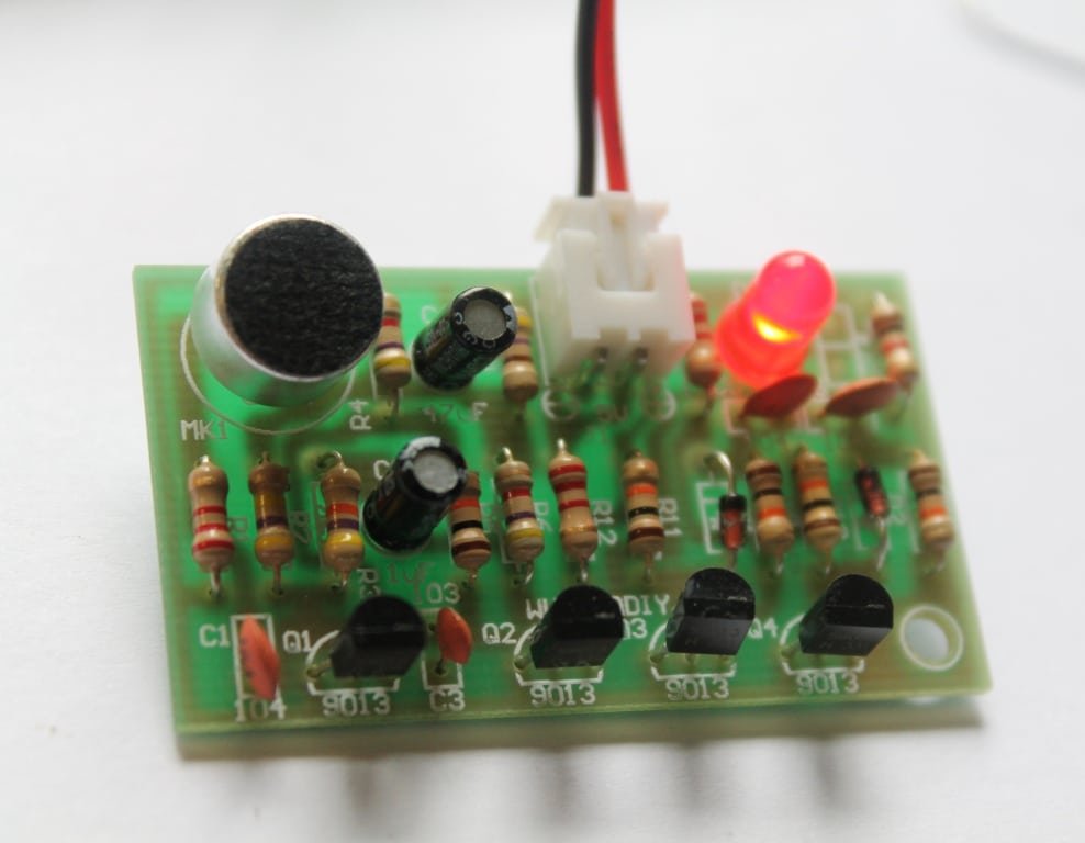
Description: Here’s a simple DIY clap switch circuit. The circuit is mainly composed of an audio frequency and a bistable trigger circuit.

Q1 and Q2 together form an amplifier circuit. MK1 (electret microphone) accepts Clap/Audio signal and that enters to transistor Q1 through the coupling capacitor C1 and enters to Q2 base through collector directly after getting amplified. And it obtains a negative square-wave which used to trigger the bistable circuit from Q2’s collector.  (more…)

Assembly guide- DIY Arduino

We are now selling the BLUE COLORED DIY Arduino kit

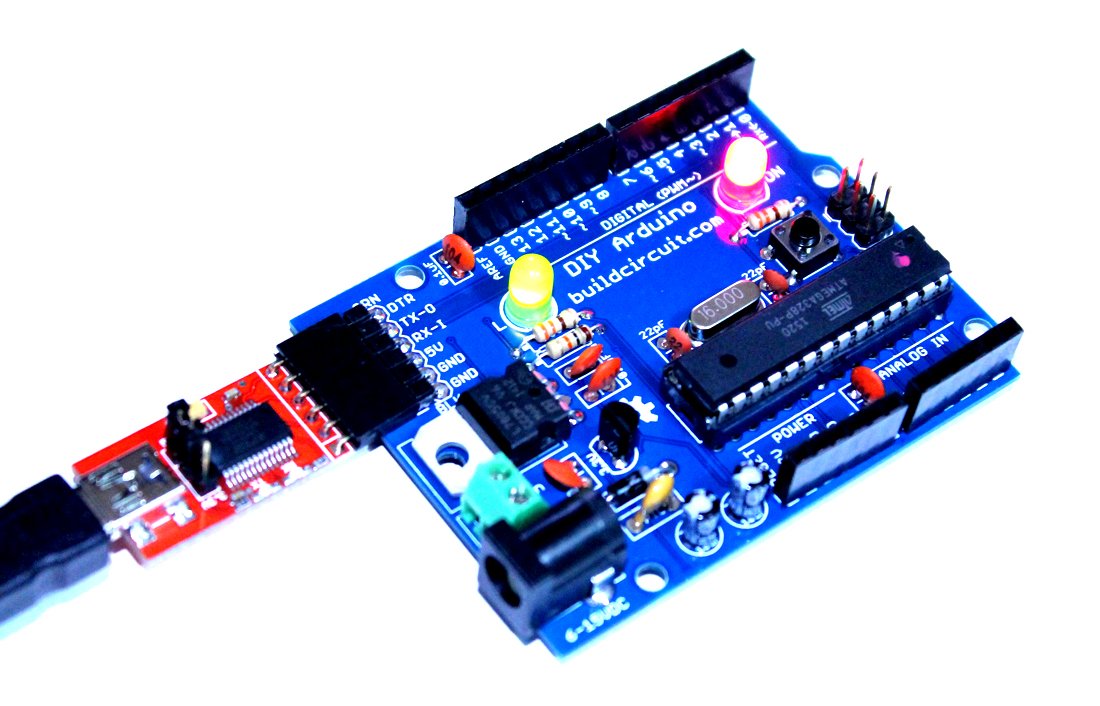
This post shows you how to assemble the DIY Arduino board.

DIY Arduino Kit for Beginners (8)

The assembly process is straight forward. It can be easily assembled if you follow the silkscreen indicators(labels) and have beginning experience with a soldering iron. You will need to read the resistor bands or use a multimeter to determine the resistor sizes.

Note: You will need either an FTDI Basic or FTDI cable to load code using the Arduino IDE.

Kit Includes:

  • 1 x Arduino-Compatible plated through holes (PTH) Kit PCB
  • 1 x ATMega328 with Optiboot bootloader
  • 1 x L78L33 3.3V Voltage Regulator
  • 1 x 5mm Green LED
  • 1 x 5mm Red LED
  • 2 x 330Ohm Resistor
  • 1 x 10kOhm Resistor
  • 1 x 16MHz Crystal
  • 2 x 22pF Ceramic Capacitors
  • 5 x 0.1uF Ceramic Capacitors
  • 2 x 10uF Electrolytic Capacitors
  • 1 x LM7805 5V Regulator
  • 1 x Diode 1N4001
  • 1 x Resettable Fuse PTC (300mA)
  • 1 x 28-Pin DIP Socket (To seat your ATMega)
  • 1 x Push Button Reset Switch
  • 2 x 6-Pin Female Headers
  • 2 x 8-Pin Female Headers
  • 1 x 6-Pin Right Angle Header (To connect your FTDI Basic)
  • 1 x 0.1uF Capacitor
  • 1 x DC Barrel Jack
  • 1 x 2-pin screw terminal
  • 1 x 6 pin ICSP header

Description of this DIY Arduino board is available on this page.

Assembly video: 

See all the assembly images on Flickr

You can see all the assembly steps on this post.

Step 1: Start with the resistors 10K(Brown-Black-Orange) and 2 pcs 330R (Orange-Orange-Brown).

1 Fix all the resistors

You can see all the assembly steps on this post.

Step 2: Then fix the 16Mhz crystal oscillator, 1N4001 diode and 2pcs of 22pF capacitors.

4- Fix 22pF capacitor

You can see all the assembly steps on this post.

Step 3: Fix 5 pcs of 0.1uF capacitor. The image shows only 4pcs. I actually forgot to solder the last one, which is right after the Vin point.

5- 4pcs of 0.1uF capacitor-another angle

capacitor

The left over(remaining) 0.1uF capacitor

Step 4: Solder LM7805 voltage regulator, 3.3V regulator and the tactile switch.

8- fix 3.3V regulator

You can see all the assembly steps on this post.

Step 5: Now fix the PTC resettable fuse (300mA), 28pin IC header, 2 pin screw terminal and 2pcs of 5mm LEDs.

11- Fix 28 pin IC header and the LEDs

You can see all the assembly steps on this post.

Step 6: Fix the DC barrel, 2 pcs 10uF capacitors, 6 pin male header (for connecting FTDI basic module) and ICSP header.

17- close up

Step 7: Finally, fix the stackable headers and Arduino UNO chip. Your Arduino is now ready.

19- The DIY arduino is now ready

You would need a FTDI basic module to program the Arduino board. The following image shows how to connect the FTDI basic module.

21- FTDI connection to Arduino and computer

You can see all the assembly steps on this post.

See all the assembly images on Flickr

See the output below:


You can purchase this kit from here:

BC-2138

Do-It-Yourself (DIY) Arduino- Make Your Own Arduino

US $14.95
This kit contains everything you need to build

Assembly- Breadboard power supply DIY kit

button_prev_page

This is the assembly tutorial of ‘breadboard power supply DIY kit’. You can get all the details of this kit at this link.

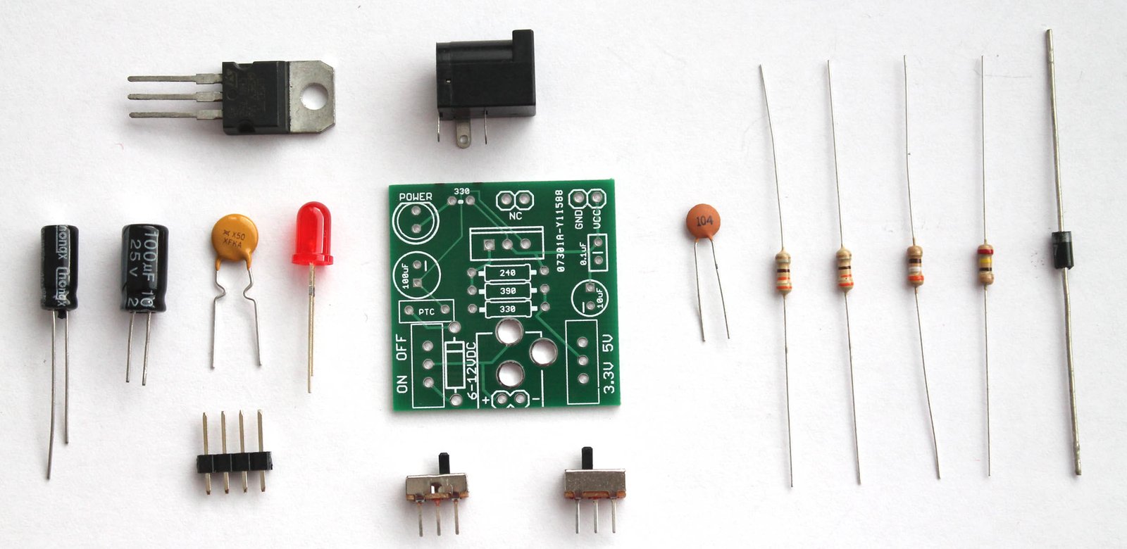
You will get the following components with the kit package. You can purchase this kit at buildcircuit.com.au. The web store is operated by BuildCircuit team.

Breadboard power supply- components

try this also

Look at the PCB below.You can see the silkscreen indicators/labels of the components. If you follow the labels correctly, you can easily assemble all the components on to the circuit board.

PCB

PCB dimension: 31.75mm x 31.75mm

Step 1: Start with resistors. Solder the three resistors- 330R, 390R and 240R. Click on the resistors to get the color code.

Step 1- solder resistors 330R, 240R and 390R

Step 2: Then, fix the diode 1N4001. You can also use 1N4004 or 1N4007. All work the same way.

Step 2 Solder 1N4007 diode

Step 3: Fix 0.1uF (code-104) capacitor.

Step 3 Solder 0.1uF capacitor

Step 4: Fix the 2pcs of SPDT switch. One switch is for ON/OFF function and the other is for switching 3.3V and 5V.

Step 5 Solder another SPDT switch

Step 5: Fix the 5mm red LED. It works as a power indicator.

Step 6 Solder 5mm LED

Step 6: Fix the PTC resettable fuse (500mA). This is a handy little device that can save your system from burning. A resettable fuse (also known as a PTC) is a resistor that has very unique properties.

For this kit, if your circuit tries to draw more than 500mA of current (if you have a bad short for instance) the PTC would ‘trip’ (by heating up). The increased resistance (trip state) would break the circuit and allow only a small leakage current.

Step 7 Solder resettable fuse 500mA

Step 7: Solder the 330R resistor. It works as current limiting resistor for the 5mm LED.

Step 8 Solder the last 330R resistor

Step 8: Solder 100uF and 10uF capacitors. Please be careful with the polarity. Wrong polarity will burn the components. The silkscreen indicators should help.

Step 9 Solder 100uF and 10uF capacitors

Step 9: Solder the LM317 chip and DC barrel.

Step 10 Solder LM7805 and DC barrel

Step 10: There are 2pcs of 2-pin male header for fixing the circuit board into the breadboard holes. You need to solder them as shown on the image below.

Step 11 Solder the male headers for breadboard

Give a close look.

Step 11-Close up

Step 12: Fix the power supply into your breadboard using the male headers. Power up the circuit with any DC supply (6-37V), it will give two outputs- 3.3V and 5V(one at a time).

Step 14- 3 Powering up the breadboard power supply - Copy

The kit is ready to use for your projects. Fix your project components on the remaining part of the breadboard.

Step 13 Powering up the breadboard power supply

Recommended links:

  1. How to make power supply using LM317 ?
  2. Assembly Tutorial
  3. Buy the kit at buildcircuit.net
  4. Video- How to make a LM317 power supply
  5. Images on Flickr
  6. Schematic-breadboard-power-supply

You can buy this wonderful DIY kit at buildcircuit.net. BuildCircuit.ORG is the online store owned and operated by BuildCircuit team.

try this also

Search for products

Back to Top
Product has been added to your cart