DIY KIT 55- TDA2282 based audio amplifier DIY kit

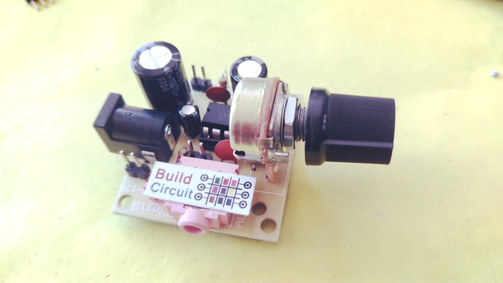
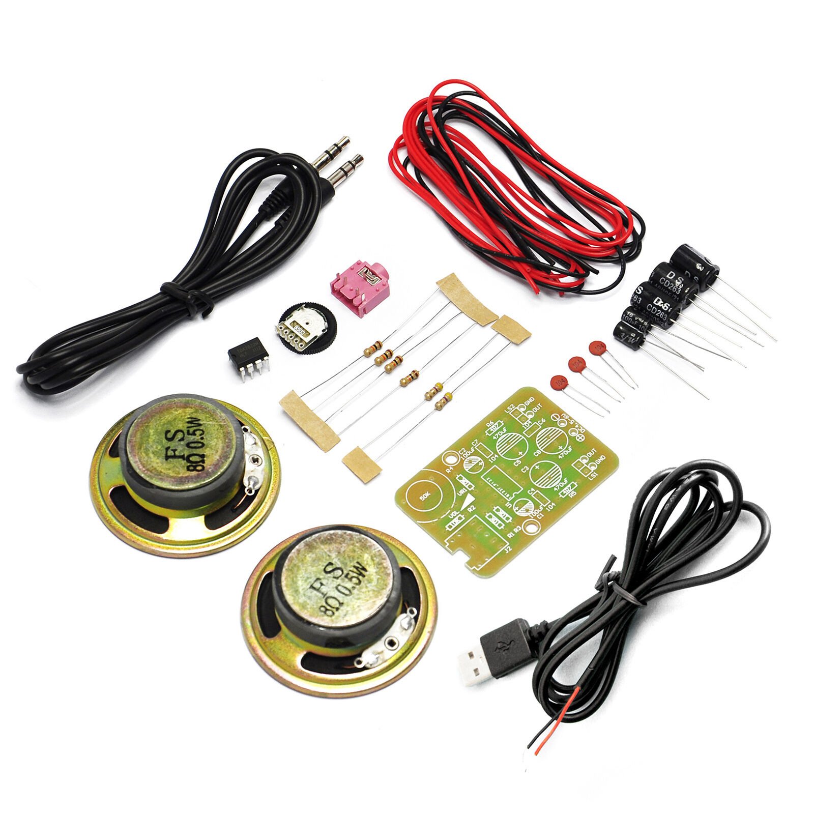
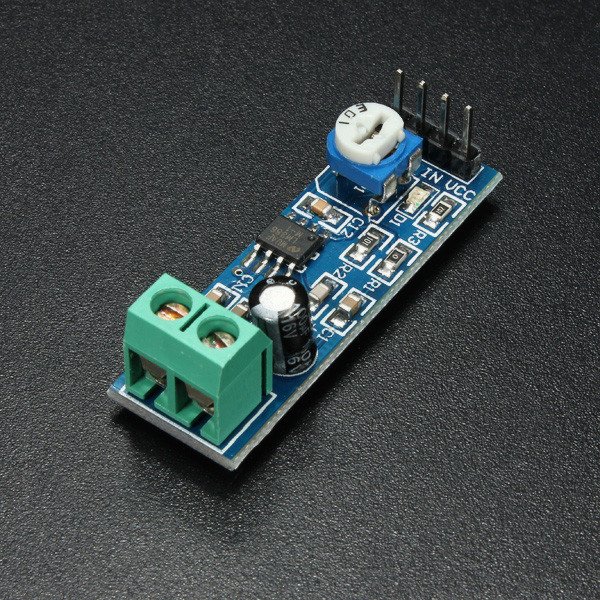
This is yet another audio amplifier project. It is based on TDA2282 chip. The TDA2822M is a monolithic integrated circuit in 8 lead Minidip package. It is intended for use as dual audio power amplifier in portable cassette players and radios. Datasheet of TDA2282

You can see all the assembly images below. You can see the images on Flickr also. 


DIY KIT 52- LM386 based audio amplifier

I have written several projects related to LM386 based audio amplifier. LM386 is a versatile and a widely popular audio amplifier chip. The LM386M-1 and LM386MX-1 are power amplifiers
designed for use in low voltage consumer applications. The gain is internally set to 20 to keep external part count low, but the addition of an external resistor and capacitor between pins 1 and 8 will increase the gain to any value from 20 to 200. The inputs are ground referenced while the output automatically biases to one-half the supply voltage. The quiescent power drain is only 24 mW when operating from a 6-V supply, making the LM386M-1 and LM386MX-1 ideal for battery operation. (more…)

DIY KIT 40 – TDA2822M Audio Amplifier DIY Kit

AMP-1 amplifier uses TDA2822M  as an amplifier chip. This chip is STMicroelectronics (ST) developed dual-channel monolithic power amplifier IC, usually used in the pocket cassette player (WALKMAN), tape recorders and multimedia speaker for the audio amplifier. It has a simple circuit, produces good sound quality, it has a wide voltage range and other characteristics that can work in stereo and bridge amplification (BTL) circuit form. (more…)

DIY KIT 32- FM receiver DIY Kit

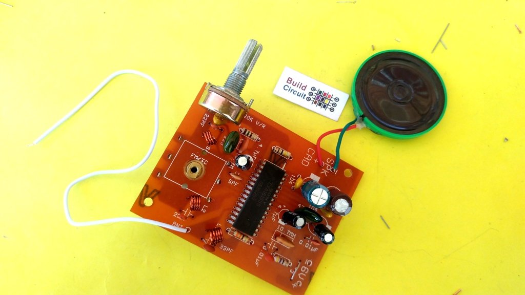
This is yet another FM receiver DIY kit for electronics beginners and hobbyists. It uses the chip CXA1619. The kit package comes with all the components required to build the kit. The schematic and description is shown below:

This is the PCB of the kit. The silkscreen labels can guide you through soldering.

The PCB of the kit

This is what you get in the kit package:

Click on the images below to see all the assembly steps. You can also see these images on Flickr.

Audio amplifier using LM386

Description: The LM386 is an audio amplifier designed for use in low voltage consumer applications. The gain is internally set to 20 to keep external part count low, but the addition of an external resistor and capacitor between pins 1 and 8 will increase the gain to any value from 20 to 200.

(more…)

Arduino controlling the WTV020SD-16P Evaluation kit

WTV020SD-16P Evalation kit (3)

This article shows how you can test WTV020SD-16P module using Arduino and WTV020SD-16P evaluation DIY kit. If you have come to this page directly from a search engine, we recommend you to visit these pages to understand this project:

Connecting the WTV020SD-16P evaluation kit to Arduino:

You can see there is a 6 pin female header for connecting the kit to Arduino.

WTV020SD-16P Evalation kit (3)

  • 5V connects to 5V pin of Arduino
  • RST connects to Digital Pin 2 of Arduino
  • P04 connects to Digital Pin 3 of Arduino
  • P05 connects to Digital Pin 4 of Arduino
  • P06 connects to Digital Pin 5 of Arduino
  • GND connects to GND pin of Arduino

After connecting the kit to Arduino, load some AD4 format files on to your MicroSD card. You can Download the AD4 audio sample files. And, then stack the WTV020SD-16P module over the stackable header of the kit. Please note that the LM386 Audio amplifier module and the connected speaker are optional. The speaker connected directly to the kit is sufficient to hear the audio. But, the Audio amplifier module amplifies the sound and you can hear it more clearly.

1

See all the flicker images

SAMPLES FILES 2

Upload the following sketch to Arduino:

Optional Link

The output of the project:

When you upload the sketch to your Arduino, the kit starts playing music one after another. After all the songs are played, it loops back to the first one. Download the AD4 audio sample files.

wtv020sd16p.asyncPlayVoice(0);
plays song 0000.AD4
wtv020sd16p.asyncPlayVoice(1);
plays song 0001.AD4
delay(8000);
Delay sets the duration of song to be played.
wtv020sd16p.stopVoice(); 
This command stops the audio
wtv020sd16p.asyncPlayVoice(0); // plays song 0, 0000.AD4
delay(8000); // play time duration
wtv020sd16p.stopVoice();

– See more at: http://www.buildcircuit.com/arduino-controlling-the-wtv020sd-16p-evaluation-kit/#sthash.V9gJ52Md.dpuf

Related documents:

Assembly Guide- WTV020SD-16P evaluation board- DIY kit

17- The kit in action

This post shows you how to assemble the WTV020SD-16P evaluation board. You can get full description of this kit on this page.

The assembly process is straight forward. It can be easily assembled if you follow the silkscreen indicators(labels) and have beginning experience with a soldering iron. You will need to read the resistor bands or use a multimeter to determine the resistor sizes.

Kit includes:

  • Bare PCB with silkscreen indicators.
  • 4 x reset tactile switch
  • 2 x 10uF electrolytic capacitors
  • 2 x 0.1uF ceramic capacitors
  • 1 x PTC resettable fuse
  • 2 x 3mm LED
  • 1 x DC barrel
  • 1 x 500 Ohm variable resistor
  • 1 x 1N4001 diode
  • 1 x 3.3V regulator chip (L78L33)
  • 1 x LM7805 (5V regulator chip)
  • 1 x TO-220 heat sink for LM7805
  • 1 x 4 pin male header
  • 1 x 6 pin female header
  • 2 x 8 pin female headers for stacking the music module
  • 1 x 470R resistor
  • 1 x 330R resistor

You need would other components that are not included along with the kit package and you need to buy those separately.

Buy these components separately:

You can get full description of this kit on this page.

Now, you can start the assembly process. We have skipped some steps on this post. If you want to see all the steps, please check this tutorial.

Step 1: Solder resistors 330R and 470R.

2- Fix 330R and 470 Ohm

See all the steps

Step 2: Solder 2 pcs 0.1uF ceramic capacitors, 3mm LEDs, 3.3V regulator and 1N4001 diode.

6- Solder 3.3V regulator

See all the steps

Step 4: Solder all the tactile switches.

7- Solder 4pcs of tactile switches

See all the steps

Step 5: Solder 2 pcs 10uF capacitors and 300mA resettable PTC fuse.

8- Solder capacitors and resettable fuse 300mA

See all the steps

Step 6: Solder 500 Ohm variable resistor. The image shows 103 (which is 10K) which is incorrect. We send you 500 Ohm variable resistor.

9 - Solder 500Ohm variable resistr

See all the steps

Step 7: Solder DC barrel, 6 pin female header and 4 pin male header
11- Solder DC barrel

See all the steps

Step 8: Connect a 8 Ohm speaker and solder 2pcs of 8 pin female header for stacking the WTV020SD module.

13- Solder stackable header

See all the steps

Step 9: Solder LM7805 regulator chip.

15- The kit is ready

See all the steps

Step 10: Stack WTV020-16P music module over the female headers. Your evaluation kit for wtv020sd module is ready. Simply, power the board with a 6-9V power supply and play AD4 format music files.

17- The kit in action

See all the steps

Optional:

You can connect an LM386 based audio amplifier to the kit. The amplifier will amplify the audio for you.

Click here to watch the video of the kit with the audio amplifier connected.

Output video:

 Related documents:

Gallery- WTV020SD-16P evaluation board- DIY kit

WTV020SD-16P evaluation board- DIY kit

17- The kit in action

BuildCircuit has previously published several articles about WTV020SD-16P, the best and the cheapest music module ever made for electronic enthusiasts. If you have never worked with wtv020sd-16p module, we recommend you to check out these articles. This time, we have made a very simple evaluation board for testing the wtv020sd module. It works both with and without Arduino. Click here to see the kit experiment with Arduino.

Purpose of the kit: The main purpose of this kit is to test the WTV020SD-16P music module. You just need to stack the module over the stackable header placed on the board, insert a MicroSD card and play the music stored. You can also connect it to your Arduino and make it follow the Arduino commands.

This kit contains everything you need to build your very own WTV020SD evaluation board. Simply follow the Assembly Guide and after some basic soldering, you’ll have made a fully-functional evaluation board for wtv020sd music module. The kit package does not include a wtv020sd-16p module. So, you need to buy that separately.

Features:

  • Plays music with or without Arduino. Works in mp3 mode as well as Arduino mode.
  • Supports LM386 based Audio amplifier module.
  • Works without an external audio amplifier.
  • Works with 6-9V power supply. The circuit board has 5V and 3.3V regulators.
  • It has four switches: Reset, play/pause, previous (prev) and next.
  • Includes PTC resettable fuse to protect the circuit from unexpected high current.

The kit package includes the following components:

  • Bare PCB with silkscreen indicators.
  • 4 x reset tactile switch
  • 2 x 10uF electrolytic capacitors
  • 2 x 0.1uF ceramic capacitors
  • 1 x PTC resettable fuse
  • 2 x 3mm LED
  • 1 x DC barrel
  • 1 x 500 Ohm variable resistor
  • 1 x 1N4001 diode
  • 1 x 3.3V regulator chip (L78L33)
  • 1 x LM7805 (5V regulator chip)
  • 1 x TO-220 heat sink for LM7805
  • 1 x 4 pin male header
  • 1 x 6 pin female header
  • 2 x 8 pin female headers for stacking the music module
  • 1 x 470R resistor
  • 1 x 330R resistor

You need would other things that are not included along with the kit package and you need to buy those separately.

Buy these components separately:

 Documents:

Watch the video below:

The video below shows the basic test of the evaluation board without LM386 audio amplifier. The audio level is low if we don’t use the amplifier.

Check out this video (the evaluation board with an Audio amplifier)

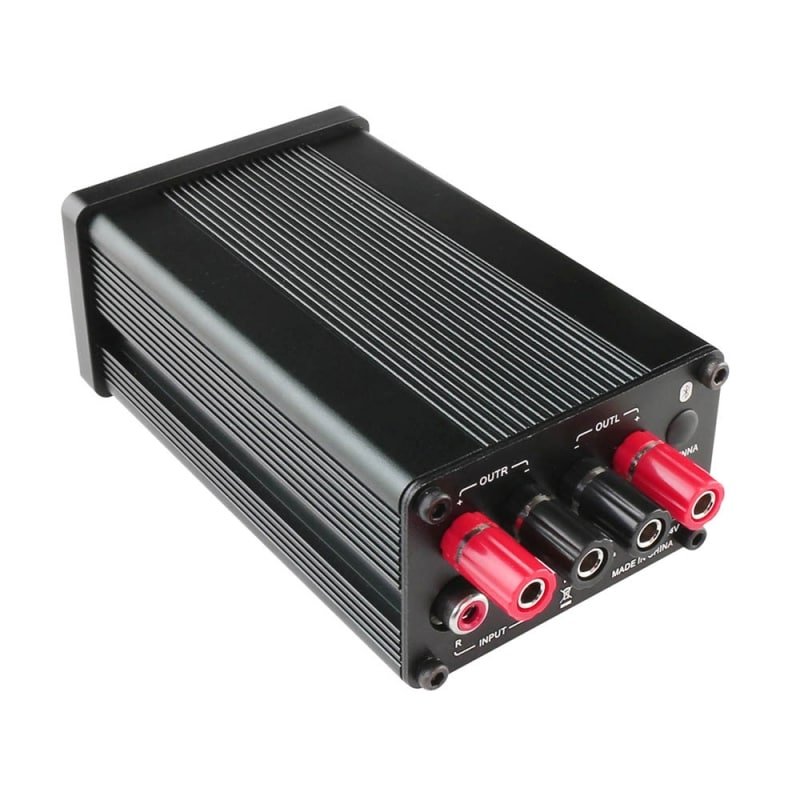
2 x 50W Class D Bluetooth Audio Amplifier Board – TSA3118

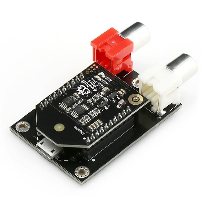
TSA3118 is a 2x50W audio amplifier board with AudioB plus Bluetooth module. It has perfect class-D architecture (based on TPA3116D2) and each channel has 50W power output. Both channels are capable of outputting nominal power simultaneously and continuously.

This board can be powered by any DC 10V-24V power supply. It can be used to drive any 4Ω or 8Ω passive speakers. TSA3118 can also be connected with our TSA1000 external audio volume control board. Users can adjust the audio volume by rotating the real knob.

It is perfect for your Hi-Fi application, the audio source can be cable input or Bluetooth. You may wish to pair up the amplifier with a mobile phone or a computer that has Bluetooth function.

Power up the amplifier board, use your phone or PC to search for a new Bluetooth device, the module will appear as “TSA3118”, you can simply pair it up without PIN. Yes, it connects automatically with your device.
You can then play your audio.

  • TSA3118 can auto-detect the Aux in/Line in Audio input. Bluetooth Audio source has a higher priority. When Bluetooth audio is paused or Bluetooth is disconnected, the amplifier will output the Aux in/Line in audio. If you want to manually select the Aux in/Line in and Bluetooth audio source, please choose TSA3116 or TSA3117.
  • Multiple TSA3118 boards can be connected together to become a multi-channel amplifier system. The Audio out port can also be connected with a subwoofer amplifier board.
  • BVC Port: BVC port can be connected with our Audio volume controller to control the Bluetooth audio volume.


TSA3118 can auto detect the Aux in/Line in Audio input. Bluetooth Audio source has higher priority. When Bluetooth audio is paused or bluetooth is disconnected. The Amplifier will output the TV audio.


TSA3118 + TSA1000, Both RCA input and Bluetooth audio volume can be controlled through BVC port

Multiple TSA3118 boards can be connected together to become a multi-channel amplifier system. The Audio out port can also be connected with a subwoofer amplifier board.

Specification:

Specifications typical @ +25℃, Powered by 21V DC, unless otherwise noted. Specifications are subject to change without notice.

Parameter

Condition

Min

Typ

Max

Supply Voltage (VDC)

10

21 24
Idle Power SD Floating

1.3W 2.5W
Standby Power SD Connected to GND

0.1W 0.3W
Maximum Current 100W @ 4Ohm

5.29A

Efficiency 50W @ 4Ohm 87% 92%
Minimum Load Impedance 3.2Ω
Switching Frequency SD Floating 394KHZ
Gain 24dB 25dB 26dB
Input Sensitivity(RMS) @4Ω, 50W, 1KHz 808mV
Input Impedance 22KΩ
Output Power @4Ω THD+N 1% 36W
@4Ω THD+N 10% 50W
Bandwidth @ ±3dB @4Ω 20Hz 20KHz
THD @4Ω, 1W, 1KHz 0.0299%
@4Ω, 10W, 1KHz 0.073%


Features:

  • Size: 6.9cm x 9.5cm
  • Bluetooth 4.0
  • Bluetooth audio volume control port(BVC)
  • Aux in/LIne in autodetect
  • Subwoofer output port
  • Working voltage: DC 10V-24V
  • Over/under voltage protection
  • Over current protection
  • Over temperature protection

Applications:

  • Personal computer
  • Background music system
  • Musical instrument amplifiers
  • Home DIY
  • Car audio

Documents:

This product can be purchased from here:

2 x 50 Watt Class D Audio Amplifier – TSA3611

This product does not have Bluetooth feature.

This is a 2x50W audio amplifier that has integrated TI’s TPA3116 as the driver. It has a perfect class-D architecture and each channel has 50W power output. This board can be powered by any DC 12V-24V power supply. It can be used to drive any 4Ω or 8Ω passive speakers. There is an ON/OFF switch and a volume knob on the front panel. (more…)

Yet another simple amplifier for your Arduino and music projects

BuildCircuit has written few articles about audio amplifier and music modules. One of the most popular examples is “Audio amplifier using LM386“. This article is about a bit advanced audio amplifier made using TDA7052A.

Download datasheet of TDA7052A

It is not wise to connect an 8 Ohm loudspeaker directly to Arduino microcontroller pins. When we calculate the current through the speaker we get : I=V/R= 5V/8 ohm=0.625A=625 mA. But microcontroller pin can only drive 20 mA to 40 mA. So, this project can solve this problem. This amplifier can be used with music modules like WTV020SD.

(more…)

Change Bluetooth Audio Amplifier Name or Audio Tone


All of our Bluetooth audio amplifier boards and Bluetooth audio receiver boards use AudioB plus module as the core bluetooth receiver module. The default bluetooth name is “BT SPEAKER”. Maybe you want change it to a special name. We just updated the AudioB plus design and breakout the programming port. Now, you can change the BT name by yourself.

Hardware and Software required:

Step 1:

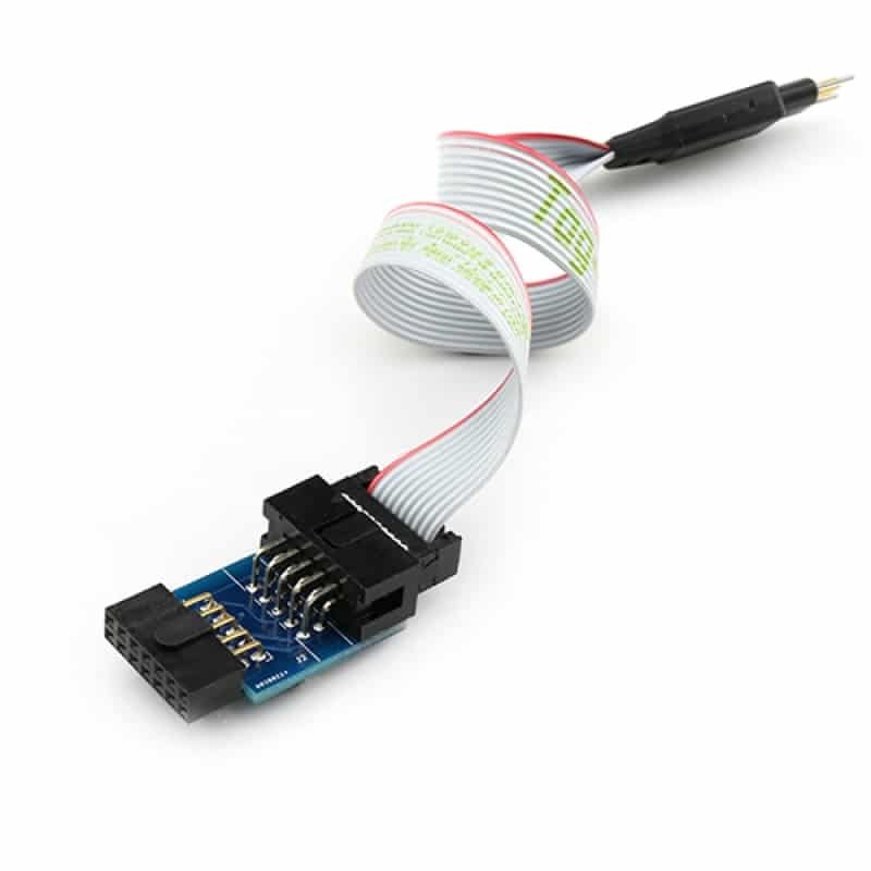
Connect the CSR USB-SPI programmer and Tag-Connect line with a AudioB Plus convert board, then connect CSR USB-SPI to your computer by a mini USB cable and windows will auto detect it and install the drivers.

Step 2:

Connect TC2050-IDC-NL’s connector to AudioB plus programming port. You need to locate the single steel alignment pin of the connector into the single hole of the PCB footprint, then press down softly to engage the spring-pin contacts. Make sure the first 6 pins have a good contact with the corresponding pads. Then the blue led and red led will flashes alternately.

Step3:

Make sure the connection is fine, then open PSTool in BlueSuite 2.5.0.

Step 4:

Choose “SPI BCCMD”, and if the connection is fine, the CSR USB-SPI device will show in “Port”, then click “OK”.

Step5:

Next, Input “name” in “Filter”, then choose the option named “Local device’s ‘user friendly’ name”, the text box on the right will show the current name of Bluetooth module(default is “BT Speaker”), if you want to change it, just input the new name in this text box.
For example, here we input “TinySine Audio” then click “Set” to complete the change. Finally, close the program.

Note:

1. If you haven’t installed CSR BlueSuite 2.5.0 on your computer, please download it here and install it. During the process of installation, you need to check the option “set debug transport the USB SPI”.

2. You may need to install the driver for CSR USB-SPI programmer on your computer.
For 32 bit system:

C:\Program Files\CSR\BlueSuite 2.5.0\drivers\win32
For 64 bit system:
C:\Program Files\CSR\BlueSuite 2.5.0\drivers\win64

Remove The Audio Tone

Hardware and Software required:

Step1:

Connect the CSR USB-SPI programmer and Tag-Connect line with a AudioB Plus convert board, then connect CSR USB-SPI to your computer by a mini USB cable and windows will auto detect it and install the drivers.

Step2:

Connect TC2050-IDC-NL’s connector to AudioB plus programming port. You need to locate the single steel alignment pin of the connector into the single hole of the PCB footprint, then press down softly to engage the spring-pin contacts. Make sure the first 6 pins have a good contact with the corresponding pads. Then the blue led and red led will flashes alternately.

Step3:

Make sure the connection is fine, then open Config Tool.

Step4:

Click “Open From Device” to read the chip information. Then goes into “Audio Tones” page after Read Device Successful. You will find 4 audio tones in the chip.

Step5:

Click “Remove” to delete 1-3 of them. You must keep at least one audio tone or will damage the chip. Then click “Write Device”.

Step6:

You have removed the audio tone successfully. Close Config Tool program and remove the CSR USB-SPI programmer from your AudioB plus module.

Remove The Audio Tone (APTX)

Hardware and Software required:

Step1:

Connect the CSR USB-SPI programmer and Tag-Connect line with an AudioB Plus convert board, then connect CSR USB-SPI to your computer by a mini USB cable and windows will auto detect it and install the drivers.

Step2:

Connect TC2050-IDC-NL’s connector to AudioB plus programming port. You need to locate the single steel alignment pin of the connector into the single hole of the PCB footprint, then press down softly to engage the spring-pin contacts. Make sure the first 6 pins have a good contact with the corresponding pads. Then the blue led and red led will flashes alternately.


Step3:

Make sure the connection is fine, then open CSRA64xxx Configuration Tool

Step4:

Please select the corresponding version of the chip in the left upper first drop-down menu, select USB SPI (180063) in the second dropdown menu, and then click  “Read Device” to read chip configuration data from the AudioB plus circuit board .


Step5:

After reading the modue information, in the most left Set Configuration in order to start: User Interface → Tones→ Event Tonesr, You can find a total of eight kinds of audio tones.

Step6:

Click “Delect” to delete any of them. You must keep at least one audio tone or will damage the chip. Then click “Write Device”.

Step7:

You have removed the audio tone successful. Close Config Tool program and remove the CSR USB-SPI programmer from your AudioB plus module.

Search for products

Back to Top
Product has been added to your cart