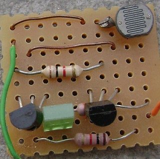
Dark sensor on breadboard

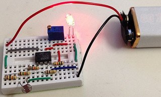
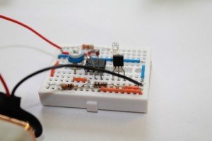
The circuit is ready for testing. Connect battery terminals and see the output. As you block light falling on LDR(Light dependent resistor), the LED glows.

OUTPUT:

[youtube]http://www.youtube.com/watch?v=qmWAgoHwy3w[/youtube]

THIS CIRCUIT IS EXTREMELY SENSITIVE TO DARKNESS. EXPERIMENT THE CIRCUIT IN A HIGHLY ILLUMINATED ROOM.

LED GLOWS EVEN IN LESS DARKNESS. Use torch light if the LED glows in less darkness. You can adjust the sensitivity of the circuit using a variable resistor in place of R3-300Ohm. Try this circuit with other resistances as well, for example, 1K, 10K and 100K, etc.

Experiments with 741- Operational amplifier

Description: This versatile 741 operational amplifier module can be used for making a dark detector using an LDR, a photo transistor and a photo diode. The amplifier has been configured in inverting mode. It compares the change in voltage at pin 2 with the reference voltage at pin 3 and gives output at pin 6 accordingly.  A general calculation and working of similar project has been explained on buildcircuit.com.  CLICK HERE for the project. (more…)

Experiments with LM358

Description: LM358 is also one of the types of operational amplifier. LM358 consists of two independent, high-gain, frequency-compensated operational amplifiers designed to operate from a single supply over a wide range of voltages.

This module can also be used for testing an LDR, a phototransistor and a photodiode. You just need to replace an LDR with phototransistor or photodiode, the circuit simply works. You can try this project using 741 IC also. (more…)

Basic RC circuit

For the circuit to work as light operated musical bell, we need to connect the SW1- switch to N/C terminal of relay. LDR has to be kept in a dark case.

AM receiver from dark sensor

In this case, LDR has been replaced with capacitor C1-0.01uF and resistor R3-1K has been replaced with L1 & VC1. In place of a LED, a Piezo Diaphragm has been kept.

We just need to add inductor, capacitor and a piezo diaphragm to convert a dark detector to an AM radio.

Water Level Indicator

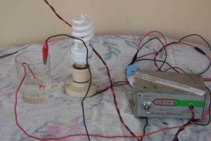
We can use the logic of making an automatic light detector to make a simple water level indicator.We just need to remove LDR from the circuit and put the wires into water, then it simply works as water level indicator. There is a specific resistance between the wires that are dipped into water and conduction of electricity through water gives biasing voltage to base of transistor.

The sensitivity can be adjusted using VR1. Put 470K variable resistance in VR1.

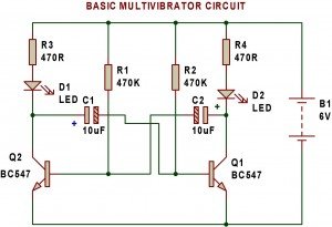
Multivibrator

A multivibrator is an electronic circuit used to implement a variety of simple two-state systems such as light
emitting diodes, timers and flip-flops.

Remote Tester

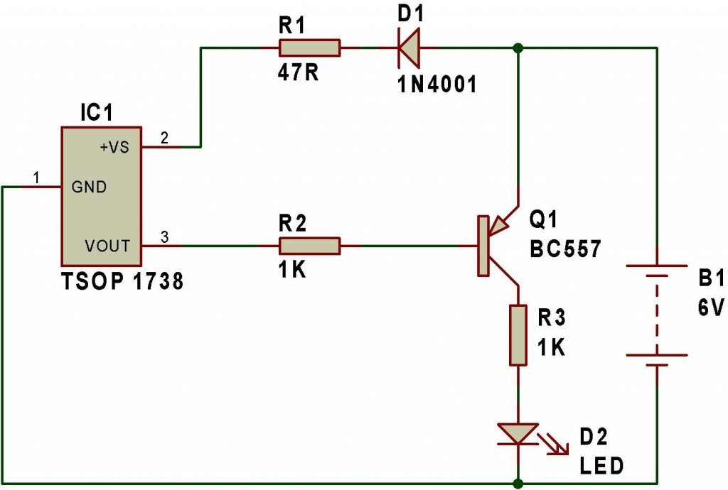
Remote tester circuit also resembles the logic of a “dark sensor (using BC557)”. LDR has been replaced with IR sensor TSOP 1738. The circuit works as a remote tester. Pressing a remote control switch near the IR sensor, switches on the LED D2.

Building a circuit on a breadboard

A breadboard is a device for testing temporary electronics projects. Components used to test a circuit can be reused for other projects. None of the components are damaged.

Almost all people start to learn electronics using breadboard because it is the simplest way of making circuit. The photograph shows a typical small breadboard which is suitable for beginners building simple circuits with one or two ICs (chips).

Dark/Light sensor using transistor

Automatic Light detector using variable resistor

A light detector senses light. As the light level increases and LDR meets the lowest threshold resistance, the circuit automatically turns on the LED D1. We can adjust the sensitivity using the preset VR1-10K.

LESS RESISTANCE(VR1)-> LESS DARKNESS TO SWITCH OFF THE LED

HIGH RESISTANCE(VR1)-> MORE DARKNESS TO SWITCH OFF THE LED

Search for products

Back to Top
Product has been added to your cart