ldr engineering
LDR Engineering
LDR (Light dependent resistor) Engineering is a technique of making several electronics circuits following the logic of a simple light and dark sensor using transistors, 555 IC and 741 IC. Out of several optical sensors, light dependent resistor can be used for making light/dark sensors. A dark sensor switches on transistor or LED whenever the incident light intensity is decreased, whereas a light sensor works in opposite way. In LDR Engineering, we first understand the working principle of any circuit using LDR, and then we replace the LDR with a fixed resistor or some other electronic component that makes the simple automatic light/dark sensor work as a completely different device. Making automatic light/dark sensor circuits using different methods can make you observe several electronics components. On the other hand, modifying those automatic light/dark sensor circuits to some functionally different circuits like touch switch,water level indicator, clap switch, etc. can make you understand about those circuits. In this article, we will see how we can use the concept of a dark sensor to make a touch and a clap switch.
Light dependent resistor:
Light dependent resistor(LDR), also called as Cadmium Sulphide (CdS) cell or photoresistor is a resistor whose value depends upon the incident light intensity. In darkness, the resistanceof LDR becomes high and in light, the resistance gets low. The resistance variation phenomenon of LDR has been taken as a base for making circuits of LDR Engineering.
Circuit 1: Dark sensor using 555
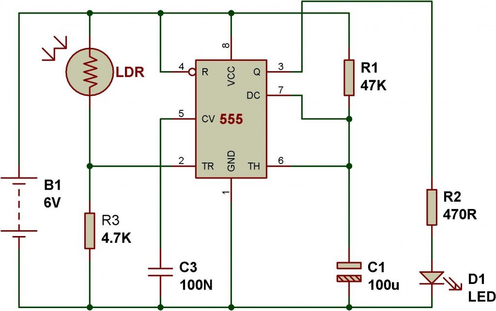
The following circuit works as a dark sensor. If the light falling on LDR is blocked, it switches on the LED D1. It has been configured in monostable mode of 555 timer which means that the circuit switches on the LED D1 for a specific time. The switching time is determined by the combination of resistance R1 and capacitor C1.
In this circuit, time (T) = 1.1xR1xC1 = 1.1x47x103x100x10-6= 5.17sec.
Circuit 2: Touch sensor using 555
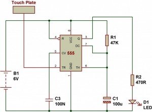
We can make the previous dark sensor circuit work as a touch sensor by making small changes in the schematic. We just need to remove the LDR, put a small wire and connect it to the coupling capacitor. Note that the electrode wire connected to capacitor C2 should be around 2-5cm long. As we touch on the wire, the circuit triggers the LED for a specific time as determined by the resistor R1 and capacitor C1. You can connect the wire to a small metallic touch plate using an alligator clip.
Circuit 3: Dark sensor using two transistors
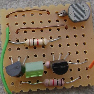
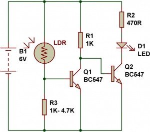
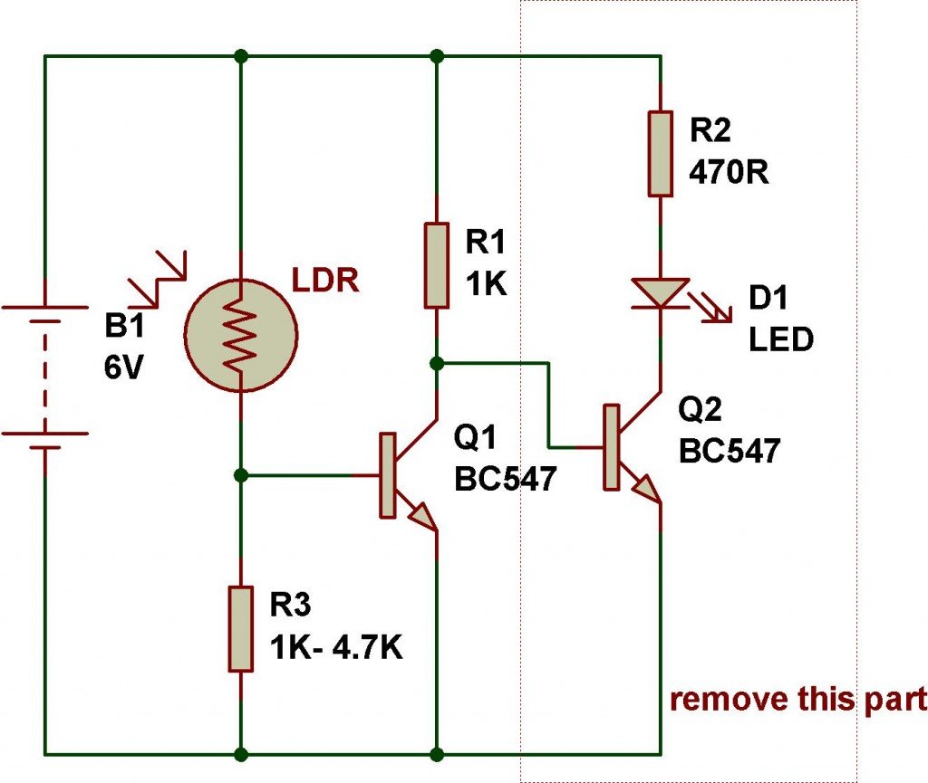
Here, we have another dark sensor that works with two transistors. When light falls on LDR, its low resistance drives transistor Q1-BC547 into conduction. This keeps transistor Q2 cut-off due to low base bias. The LED D1 does not get power as long as ambient light falls on LDR. When the resistance of LDR becomes high in darkness, transistor Q1 stops conducting and transistor Q2 starts conducting to turn on the LED.
Circuit 4: Clap switch
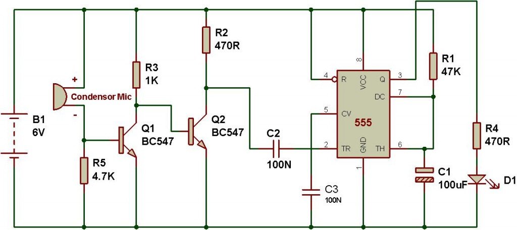
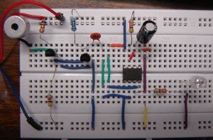
In order to make a clap switch, we have to combine the previous touch sensor and the transistorized dark sensor circuits. We also need to connect a condenser microphone in place of LDR and the collector of Q2 has to be connected to the terminal of capacitor C2. Whenever there is loud sound produced near the condenser mic, pin 2 of 555 gets triggered and it switches on the LED D1. We can adjust the sensitivity of the circuit using a variable resistor in place of fixed resistor R5.
Circuit 5: Light sensor from dark sensor
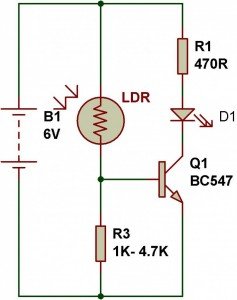
If we follow the schematic of figure 6, we can convert the two transistor dark sensor to single transistor light sensor by removing R2, D1 and Q2. The circuit works as a light sensor which switches off the LED whenever light falling on LDR is blocked.
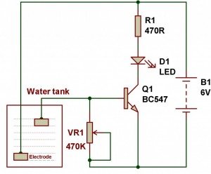
Circuit 6: Water level indicator
WARNING: NEVER TRY THIS CIRCUIT WITH AC POWER. USE 6V(4 AA size) OR 9V-PP3 battery FOR THIS EXPERIMENT.
Now, the light sensor can be easily converted to a simple water level indicator. We just need to remove the LDR, and dip the wires into water. When both wires are dipped, the circuit switches on the LED D1. We can use copper electrodes for better performance, but for normal experiment, we don’t need any electrode. VR1-470K is for adjusting the sensitivity of the circuit.
The experiments given in this article have been tested and verified. We can make several other circuits using the idea of dark/light sensor. You can explore more LDR Engineering based circuits on buildcircuit.com.




i love dis site wish i culd get d company and come and learn more about electronics
i would like to make acircuit with ldr and 68ch12 micro, the function of ldr will be to change from logic 1 to logic 0 and via versa, depending on the light lux flow, which will trigger the micro and will display different numbers, using 7 segment. any ideas?
iam searching a circuit for a line follower
any other topics related to ldr or some basic electronics plz suggest me
i would like to make a circuit with ldr and 68ch12 micro, the function of ldr will be to change from logic 1 to logic 0 and via versa, depending on the light lux flow, which will trigger the micro and will display different numbers, using 7 segment. any ideas? – See more at: http://www.buildcircuit.com/ldr-engineer/#sthash.8IIrBDNw.dpuf
please do something with a 12 volts input, we’re going to connect it to 12 volts output of a solar panel
what is dmosfet