Factors affecting Wi-Fi transmission range

The range of a Wi-Fi signal can be influenced by several factors, which can impact its coverage and strength. Understanding these factors can help you optimize your Wi-Fi network for better performance. Here are the key factors that affect Wi-Fi transmission range:

  1. Frequency Band: Wi-Fi operates in different frequency bands, such as 2.4 GHz and 5 GHz. The 2.4 GHz band has better range but can be more susceptible to interference, while the 5 GHz band offers faster speeds but has a shorter range due to higher frequencies.
  2. Obstacles and Interference: Physical obstacles like walls, floors, furniture, and appliances can weaken Wi-Fi signals. Interference from other electronic devices, microwave ovens, cordless phones, and Bluetooth devices operating in the same frequency range can also degrade signal strength.
  3. Signal Strength and Transmit Power: A stronger signal from the router’s antennas results in better coverage. Routers with higher transmit power can extend the range, but there are legal limitations on maximum transmit power.
  4. Antenna Design and Orientation: The quality and design of antennas in both the router and client devices play a crucial role in signal propagation. Positioning antennas for optimal line-of-sight and orientation can improve coverage.
  5. Number of Access Points: Deploying additional access points or Wi-Fi extenders can help expand coverage, especially in larger spaces.
  6. Wi-Fi Standards: Newer Wi-Fi standards like 802.11ac (Wi-Fi 5) and 802.11ax (Wi-Fi 6) provide better range and performance compared to older standards.
  7. Data Rate and Modulation: Lower data rates and less advanced modulation schemes can achieve longer range at the expense of speed.
  8. Channel Width: Wider channel widths (e.g., 40 MHz, 80 MHz) provide higher speeds but can reduce range due to increased susceptibility to interference.
  9. Noise and Signal-to-Noise Ratio (SNR): Higher levels of background noise can decrease the SNR, affecting the ability of devices to communicate over longer distances.
  10. Router Placement: The location of your router matters. Placing it in a central position and avoiding dense obstructions can improve signal distribution.
  11. Wi-Fi Interference: Overcrowded Wi-Fi channels in densely populated areas can lead to interference and reduced range. Selecting less congested channels can help.
  12. Environmental Conditions: Weather conditions, humidity, and atmospheric factors can affect signal propagation, particularly in outdoor or open environments.
  13. Client Device Quality: The quality and design of Wi-Fi antennas in laptops, smartphones, and other devices can impact their ability to receive signals at longer distances.
  14. Firmware and Settings: Keeping router firmware up to date and configuring settings like transmission power, channel selection, and QoS (Quality of Service) can influence range and performance.
  15. Security Settings: Certain security features like WPA3 can enhance both security and range by improving the efficiency of data transmission.

Optimizing your Wi-Fi network involves considering these factors and making adjustments to your router’s placement, settings, and hardware as needed to ensure the best possible coverage and performance throughout your space.

Factors affecting Bluetooth transmission range

Bluetooth technology has become an integral part of our wireless communication landscape, enabling a wide range of devices to connect and exchange data. However, the transmission range of Bluetooth connections can vary based on several factors. Here are some key factors that affect Bluetooth transmission range:

  1. Bluetooth Version: Different Bluetooth versions offer varying ranges. The most common versions are Bluetooth 2.1, Bluetooth 4.0 (Bluetooth Low Energy), Bluetooth 4.2, Bluetooth 5.0, and the more recent Bluetooth 5.1 and 5.2. Newer versions tend to offer improved range and better performance.
  2. Signal Strength (Transmit Power): The output power of the Bluetooth transmitter affects the transmission range. Higher transmit power can result in longer range, but it can also consume more energy.
  3. Antenna Design: The design and quality of the antennas used in both the transmitting and receiving devices play a significant role in determining the effective range. Well-designed antennas can enhance the signal strength and coverage area.
  4. Interference and Obstacles: Physical barriers, such as walls, furniture, and other obstacles, can weaken the Bluetooth signal and reduce the range. Additionally, interference from other electronic devices operating on similar frequencies (2.4 GHz) can disrupt Bluetooth communication.
  5. Environmental Conditions: Factors like humidity, temperature, and atmospheric conditions can impact signal propagation. In outdoor settings, Bluetooth range might be affected by weather conditions and terrain.
  6. Device Orientation and Placement: The relative orientation of devices (antennas) with respect to each other can affect signal strength. Positioning devices in a line-of-sight configuration can often result in better range compared to having obstacles between them.
  7. Quality of Receiver: The sensitivity and quality of the Bluetooth receiver in the target device also influence the range. A more sensitive receiver can pick up weaker signals and extend the effective range.
  8. Power Saving Modes: Devices often have power-saving modes that reduce transmission power to conserve energy. These modes can impact range when they are activated.
  9. Frequency Hopping: Bluetooth uses frequency hopping to mitigate interference. The number of hopping channels and the hopping rate can affect the ability to find clear transmission paths, thus influencing range.
  10. Transmission Rate: Higher data transmission rates may result in shorter range due to increased power consumption and a higher probability of data loss over longer distances.
  11. Device Class: Bluetooth devices are categorized into different classes based on their maximum allowable transmit power. Class 1 devices generally have the longest range, followed by Class 2 and Class 3 devices.
  12. Firmware and Software: The firmware and software implementations on both the transmitting and receiving devices can impact the range. Optimized protocols and algorithms can enhance the reliability and reach of Bluetooth connections.

It’s important to note that the actual transmission range can vary significantly based on the combination of these factors. For optimal performance, users should consider the use case, environmental conditions, and device specifications when aiming to achieve the desired Bluetooth transmission range.

Unveiling the Power of Open Source Hardware: A Collaborative Innovation Frontier

Introduction

In an era characterized by rapid technological advancements and a growing emphasis on collaboration, open source principles have transcended the realm of software and made an indelible mark on hardware development. Open source hardware (OSH) represents a paradigm shift in innovation, fostering a community-driven approach that democratizes access to technology and enables a more inclusive, creative, and sustainable future.

Defining Open Source Hardware

Open source hardware refers to the design and sharing of physical products, devices, and systems in a manner that allows anyone to view, modify, distribute, and even manufacture the technology. Similar to open source software, OSH is built on principles of transparency, collaboration, and user empowerment. The core idea is to provide the necessary information, such as schematics, blueprints, and design files, to enable others to replicate, customize, and contribute to the development of hardware projects.

Key Characteristics of Open Source Hardware

  1. Transparency: OSH projects make their design documentation openly accessible, ensuring that anyone can scrutinize, learn from, and improve upon the technology. This transparency promotes accountability and enables collective learning.
  2. Collaboration: OSH thrives on collaboration, encouraging a diverse community of enthusiasts, developers, and experts to collaborate on refining and enhancing hardware designs. This collaborative spirit often results in faster innovation and a higher quality of products.
  3. Customization: With OSH, users are not limited to a one-size-fits-all solution. They can modify, adapt, and tailor hardware designs to suit specific needs or preferences, promoting flexibility and versatility.
  4. Education: OSH projects provide an invaluable educational resource, allowing students, hobbyists, and professionals to learn about electronics, mechanics, and engineering by studying and tinkering with real-world designs.
  5. Affordability: By sharing designs and encouraging local manufacturing, OSH has the potential to reduce costs associated with proprietary hardware, making technology more accessible to a broader audience.

Advantages of Open Source Hardware

  1. Rapid Innovation: The collaborative nature of OSH accelerates innovation cycles, as countless minds contribute to refining and expanding upon designs. This leads to quicker development and more frequent breakthroughs.
  2. Global Access: OSH transcends geographical boundaries, enabling individuals and communities around the world to access and contribute to technology, bridging the digital divide.
  3. Reduced E-Waste: OSH promotes repairability and upgradability, contributing to a reduction in electronic waste by extending the lifespan of devices and encouraging responsible consumption.
  4. Community Empowerment: OSH projects foster a sense of community ownership and engagement. Local groups can come together to address unique challenges, leading to localized solutions.

Notable Open Source Hardware Projects

  1. Arduino: A popular open-source electronics platform based on easy-to-use hardware and software. Arduino has empowered countless inventors, artists, and students to create interactive projects.
  2. Raspberry Pi: A low-cost, credit card-sized computer that has sparked a revolution in DIY computing and education. Its open design has led to an expansive ecosystem of projects.
  3. OpenROV: An open-source underwater robot that enables exploration of aquatic environments. It serves as a tool for marine scientists and hobbyists alike.
  4. Open Source Ecology: Dedicated to the creation of open source industrial machines that can be used to build sustainable communities, this project encompasses everything from tractors to 3D printers.

Challenges and Future Outlook

Despite its numerous benefits, OSH also faces challenges, such as ensuring high-quality documentation, managing intellectual property, and sustaining long-term development. However, as OSH continues to gain traction, it has the potential to reshape industries, facilitate interdisciplinary collaboration, and democratize access to technology in unprecedented ways.

Conclusion

Open source hardware represents a remarkable convergence of innovation, collaboration, and democratization. By breaking down barriers to entry and enabling a diverse global community to contribute to technology, OSH is poised to drive profound changes in the way we design, create, and interact with hardware. As the world continues to embrace open source principles, the horizon of possibilities for open source hardware remains bright and limitless.

Popular Android Apps for 12CH Bluetooth Arduino module

Shortcut link for this article is https://www.buildcircuit.com/12ch

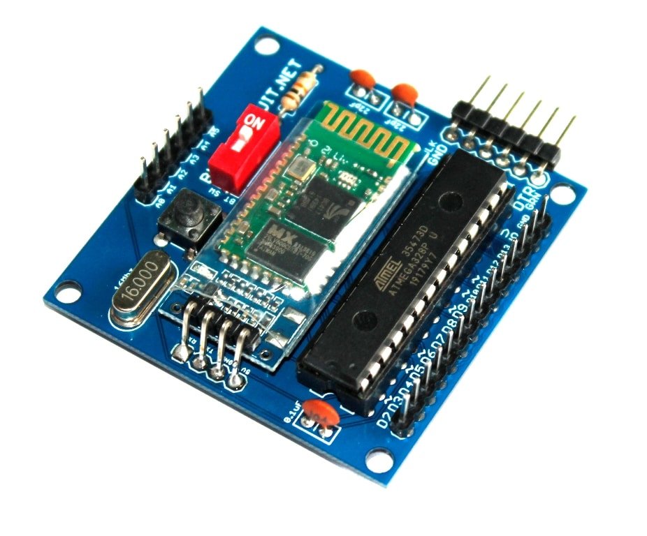
12 channels Bluetooth module for Arduino-Android communication is yet another kit for experimenting with Arduino and Android. This small module can be very effective for those learning and trying some apps using MIT media labs apps inventor .

BTRF: BTRF is a module similar to the 12CH Bluetooth module. BTRF module allows you to test Bluetooth as well as 4CH and 6CH RF modules. All the apps mentioned below do work with BTRF module also. Visit BTRF product page.

You will need an FTDI basic module to program the Arduino. The 1P DIP switch should be turned off while uploading the sketch.

This is BT module for controlling all the 12 digital pins of Arduino.


This is the BTRF module. All the apps mentioned in this article can be used for this module also. You can use this device to test the Bluetooth module as well as 6CH and 4CH RF modules.

You can make your own apps using the MIT App Invetor or use the existing apps on Google play.

When you test any new app, make sure that you read this tutorial first. Get the sketch here. This sketch will help you find out what the app is sending to Arduino. For example, some apps send characters and some send numbers. Based on the data received by Arduino, we need to write our sketch.

You can test this module with these apps:

  1. Ardroid: An Android Application for controlling any type of Arduino’s Digital and PWM Pins with the help of Bluetooth.
    It can be used to Control Arduino Uno’s Digital and PWM pins, Send & Receive text commands to/from Arduino. It offers control over all the digital pins. You can download the sketch from the app page. Download ardroid sketch


2. Arduino Bluetooth controller: Control your Arduino UNO & Arduino Nano GPIO’s and control the PWM signals via Bluetooth.
Joystick to control the robot movement, Bluetooth Terminal to send and receive the data from Arduino and save the data in sd card. You can do a lot of things with this app and obviously it works well with our Bluetooth module also.

3. Arduino Bluecontrol: Arduino Bluetooth Control is an application that allows you to control your Arduino board (and similar boards) via Bluetooth, and so to create awesome and fully customized projects, with the new features available within the app. The settings section allows you to adapt the application to your needs, through a very simple and intuitive interface.

4. E&E: Arduino Automation: Arduino Automation is an application that allows you to control devices using your Arduino Board (and similar boards) via Bluetooth or WiFi, and so to create awesome and fully customized projects, with the interfaces available within the app.

https://youtu.be/mP5ubZ1ZXSU

Related products

BC-45465
Categories:

433Mhz RF Transceiver Receiver Transmitter Module

US $5.95
  • This module uses the latest 433MHz wireless
BC-0017
Categories:

Bluetooth Module HC-05 and HC-06 for Arduino-Android Communication

US $5.95
BC-88645

BTRF kit for testing Bluetooth and RF modules

US $6.50
  • This is a basic Arduino board with

10 factors that affect the transmission range of DIY FM Transmitters

BuildCircuit sells several types of FM transmitters for electronics beginners and hobbyists. Some are for short-range and some for long-range transmission. Sometimes, customers complain that they didn’t get the mentioned quality or the required range of transmission. In this article, I am explaining 10 factors that affect the transmission range as well as the transmitted sound quality of DIY FM transmitters.

  1. Design of the FM transmitter: Some hobby FM transmitters are designed with 3 transistors and 3 inductors and some are designed with only one transistor and one inductor. All the FM transmitters with 3 transistors have an audio amplifier circuit whereas the single transistor FM transmitters have only the oscillator circuit, there is no extra amplification for frequency modulated signal. That’s why the transmitters with 3 transistors perform better than the other one. The resistors and the capacitors placed in the circuit have a huge role in determining how far the signal can go. Usually, the designers of the transmitter have a tentative range in their minds. Based on their objective, they choose the components or design the PCB in such a way that their transmitter would transmit the signal up to a certain range with a certain quality. For example, we usually see S9018(AM/FM Amplifier, Local Oscillator of FM/VHF Tuner) and S9014(for pre-amplifier) transistors in most of the FM transmitters. If you see their datasheets, you will know why they are used.

2. Antenna length: I have noticed that increasing the length of the antenna also extends the range of transmission. I tested the long-range 3 transistor FM transmitters with a 20cm long antenna first and it could transmit up to 100 meters, but when I increased the length to 60cm, the signal was transmitted up to 500 meters easily. If you a longer antenna in any FM transmitters, you get better reception and they travel farther.

3. Type of FM receiver- digital or analog: Digital FM receivers are far better than analog receivers to test the transmitters. The first advantage, we know the exact frequency the transmitter is transmitting to the receiver.  We can search for a free frequency on a digital FM receiver than on an analog one. If we can find a free frequency, we can use that for transmitting our signal without interrupting the commercial FM broadcast signals. It is illegal to interrupt the commercial FM stations in several countries.

In analog FM receivers, the tuning is not precise. The transmission from two commercial FM broadcasts also overlaps with each other.  When the transmission signal is strong, it overlaps the commercial broadcast signals and the audio is heard clearly on the receiver. Once we go far away from the transmitter(beyond the transmission range), the signal fades away and the commercial broadcast is heard again. In order to eliminate the overlapping of signals and distortion, it is recommended that we use a digital FM receiver.

4. Antenna of the FM receiver: Most of the commercial FM receivers come with a telescopic antenna. Their reception is excellent. It is recommended that you use a receiver with a telescopic antenna. When we use the FM feature of a mobile phone, the reception is not as good as the commercial FM broadcasts. However, you can use your phone to test the transmitter. But, there is no guarantee that the phone’s FM receiver can receive the signal to the maximum transmission range.

5. Power: If a transmitter has a power supply rating from 3V to 9V, the transmission is stronger at 9V than at 3V. At 3V, you will not get the same signal strength as you would get with a 9V battery.

6. Transmission method- voice or audio: If you transmit the FM signal connecting it to an audio source, for example, a mobile phone or an mp3 player, the transmitted audio signal is stronger than the voice-activated signal. A voice is converted to an electrical signal by the electret microphone, that electrical signal is oscillated and transmitted as an electromagnetic wave, it would never be as strong as the direct audio signal. The audio signal is an electrically activated signal which can be controlled by a volume controller also and amplified according to our needs. Therefore, audio signals directly fed from an audio source are transmitted farther than the normal voice signal.

7. Volume controller- audio booster: Two of our FM transmitters have a volume controller. I have noticed that the volume controller contributes to the strength of the transmitted signal which eventually determines how far the signal would travel. The following transmitters have a volume controller:

a. FM transmitter with 3 transistors- Basic (with no tuning)

b. FM transmitter with 3 transistors- Advanced (with tuning)

8. Transmitter location: Where are you transmitting from? Your FM transmitter will give better results in an open space rather than in an urban area with a lot of buildings or obstacles. Make sure that you transmit the signal from a height (if possible) so that the signal can travel farther. I tested all of my transmitter from a height (7-10m), usually the second or third floor of a building, and also tested them from the ground floor, I found the transmission quality and range vary drastically. Testing the transmitter from a height gives the best result, that’s why commercial FM stations’ antennas are kept in hills or on top of buildings.

9. The transmitting or receiving frequency: The frequency we are transmitting to should be free in order to avoid the overlapping of signals. Usually, when we use an FM transmitter without a variable capacitor or variable inductor(for example, FM transmitter with 3 transistors- Basic), the transmitter transmits its signal at a random frequency, which we cannot change. For example, the FM microphone and FM transmitter with enclosure do not have a variable capacitor or inductor.  That completely restricts the transmitters from changing their frequency which ends up overlapping the commercial FM signal. It is very important the transmitter transmits to a free frequency that is not used by commercial stations. If we transmit to an occupied or a closer frequency, there is a high chance of hearing distortion. As we go far away from the transmitter, the commercial FM overtakes its original frequency and our FM signals fade away.

These transmitters do not  have a variable capacitor or inductor

10. Weather: Weather has impacts on the capacitance and inductance of the circuit. Even negligible change in its electric parameters can drift the frequency of the transmitter. The wind, atmospheric pressure, temperature and humidity also have effects on the transmission. Please read these three interesting articles:

We are selling these FM transmitters

Sold out
BC-56145

Type 1- Long range DIY FM transmitter with 3 transistors and 3 inductors

US $11.95
  • Long-range FM transmitter: 100m-500m. Tested several times
BC-4614345

Type 2- Long range DIY FM transmitter with 3 transistors and 3 inductors

US $8.38
  • Long-range FM transmitter: 100m-300m. Tested several times

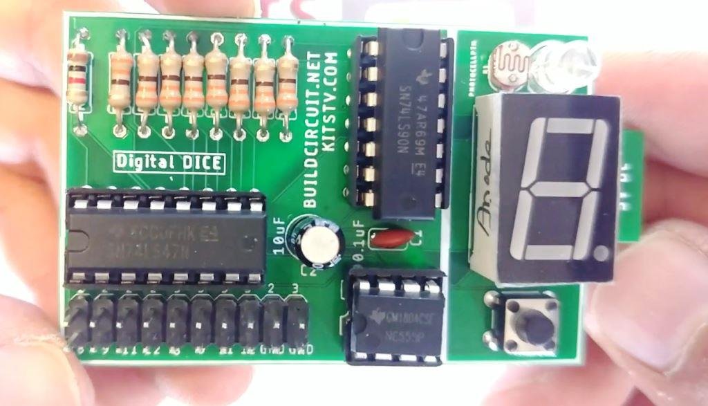
DIY KIT 68- A digital dice using 74LS47, 74LS90 and seven segment display

This is a different type of digital dice. We have previously seen electronic dice with 7 LEDs. In this project, we have a seven-segment display, not LEDs.

When you press the tactile switch the numbers increase from 0 to 9, and when the switch is released it stops at a random number. Using the 2 jumpers, you can display the numbers from 0 to any number, for example, from 0 to 1 or 0 to 5 or 0 to 8 or 0 to 9. (more…)

DIY KIT 67- How to build Jaycar’s electronic dice DIY kit

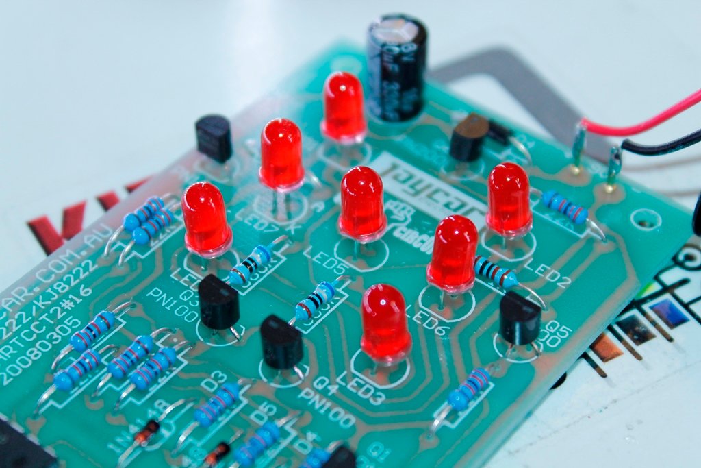
This is yet another electronic dice project from Jaycar. When you press the RED button on the PCB, all 7 LEDs flash for a while and the LEDs that stay on will represent numbers between 1 and 6. This is a basic learning kit for electronic beginners. Basic soldering skill is enough to build the kit.

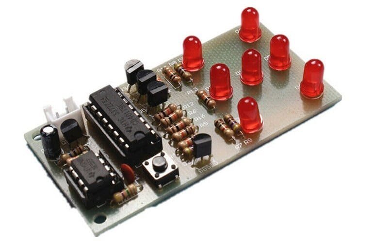
This kit is similar to an electronic dice kit from eBay. Check it out. 

Watch the video below to see all the assembly steps:

The video published below is documentation of good images. The images will help you assemble the kit easily.

You can see all the images below. All the images can be viewed on Flickr.

Download Jaycar’s Short Circuits Volume 1, 2 and 3:

Volume 1: https://www.buildcircuit.com/wp-content/uploads/2020/11/Short-Circuits-Volume-1.pdf

Volume 2: https://www.buildcircuit.com/wp-content/uploads/2020/11/Short-Circuits-Volume-2.pdf

Volume 3: https://www.buildcircuit.com/wp-content/uploads/2020/11/Short-Circuits-Volume-3.pdf

DIY KIT 66- Basic electronic dice with 7 LEDs

This is yet another CD4017 and NE555 based digital dice with 7 LEDs. When you press the tactile switch, the LEDs start flashing and stop with a pattern that represents a number between 1 to 6 like real dice. The display will always random.

[ytvg_container layout_img_size=”maxres” popup_ads_enabled=”true” main_font_weight=”” heading_font_weight=”” meta_font_weight=”” data=”%5B%7B%22name%22%3A%22Kit%20assembly%20video%20tutorial%22%2C%22urls%22%3A%22https%3A%2F%2Fyoutu.be%2FcxRttGrZW0c%22%7D%5D” popup_width=”1200px” popup_ads_google_ads_client_id=”ca-pub-3959191968523970″ popup_ads_google_ads_slot_id=”7854790433″ text_color=”#000000″ main_font=”Raleway” main_color=”#000000″ title_color=”#000000″ popup_link_color=”#ee1133″ main_font_size=”16px” main_font_line_height=”20px” heading_font_size=”20px”]

DIY KIT 65- NE555 based sound generator DIY kit with a photoresistor

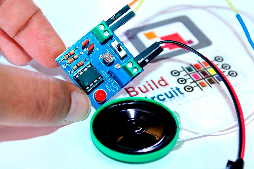
This is yet another NE555 based DIY kit for electronics beginners. A long time ago, I had published this project on this page: https://www.buildcircuit.com/sound-generator/

The electronic kit presented in this article is exactly the same circuit that I had published previously.

The circuit is an astable mode timer. The output frequency of the NE555 varies with the change in resistance of the photoresistor. When you block the light falling on the photoresistor, its resistance drops and that contributes to the change in frequency of NE555. (more…)

DIY KIT 64- ClockIt digital clock DIY kit using Arduino

[adrotate banner=”2″]

[adrotate banner="2"]
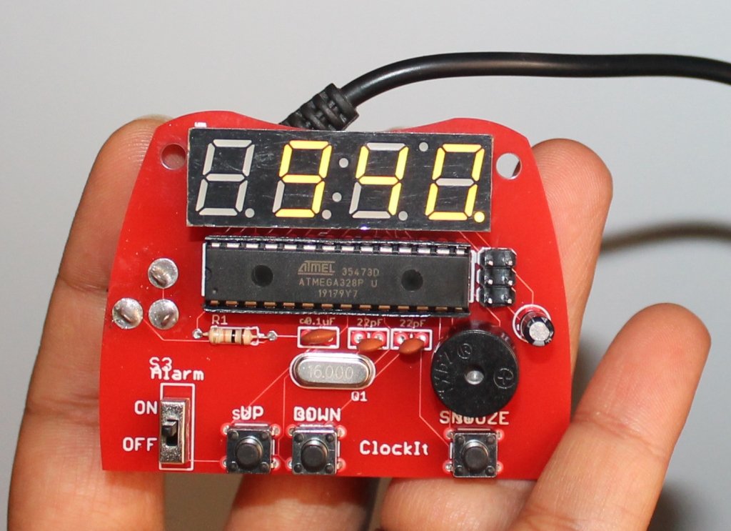
This is a great kit to learn the basics of soldering. The Sparkfun ClockIt is a basic alarm clock with buzzer based on the ever-popular ATMega328. If you’re just learning how to solder, this kit should take you 15-20 minutes. If you’re a weathered pro at soldering, this is a great relaxing build that should take 5-10 minutes. (more…)

DIY KIT 61- Digital clock DIY kit with thermistor and photoresistor

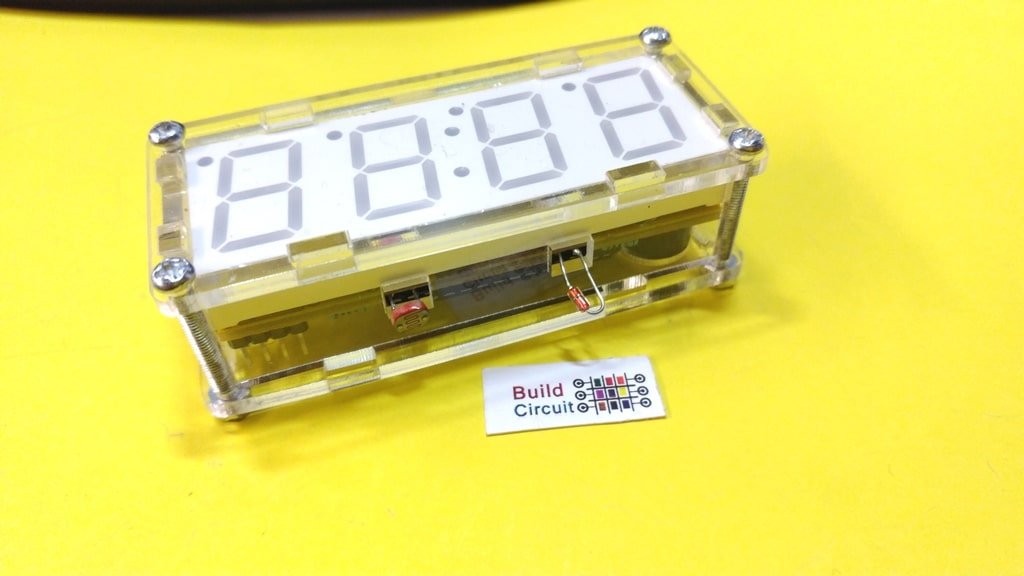
This is yet another digital clock DIY kit for electronics beginners. I have previously published several posts related to the digital clock. This kit is no different from those kits, it also displays time and the additional functions and temperature display and alarm. It also has a photoresistor which makes it sensitive to ambient light, the clock will automatically be brighter during the day than at night. The display is 0.8 inches big. With a transparent case, components can be well protected and the clock looks stylish. It is a perfect kit for electronic DIY enthusiasts, school training lessons, etc. (more…)

DIY KIT 60- Digital clock kit-II

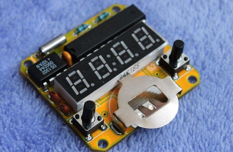
This digital clock kit looks very much similar to this kit, the kit is actually slightly advanced than the previous kit. It has enough functionalities like any other regular clock. It is very accurate. It is an easy to build kit and perfect to start to develop your soldering skills. It uses the chip AT89C2051. (more…)
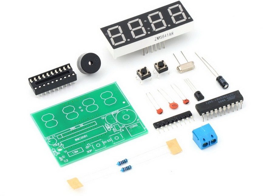
DIY KIT 59- How to assemble DIY digital clock kit ?

If you have come to this page directly from a search engine, visit this page first to know about this DIY digital clock kit.

This assembly tutorial explains how to assemble the DIY digital clock kit.

You will get the following components in the kit package:


You will need basic soldering skills to assemble the kit. If you follow the PCB silkscreen labels, you can easily solder the kit.

Step 1: Solder two Resistors and capacitors 30pF(code-30) and 0.1uF (code-104).

Step 2: Solder the other 30pF capacitor also.

Step 3: Solder the 12Mhz crystal oscillator.

Step 4: Solder 2pcs tactile switches

Step 5: Solder SS8550 transistor.

Step 6: Solder IC socket and SIP-9 1k resistor. The resistor is used to control current in the seven segment display

Step 7: Solder 10uF capacitor. Be careful with the capacitor polarity. Insert positive pin of the capacitor in the hole marked +

Step 8: Solder 5mm screw terminal. You will use this terminal to connect battery.

Step 9: Solder the buzzer. Note the polarity of the buzzer.

Step 10: Solder 4 digit seven segment display

Step 11: Insert the microcontroller chip in the IC socket

Step 12: Connect a 9V battery connector to the screw terminal. You can now use the digital clock.

Digital clock DIY kit is available at www.buildcircuit.com.au.

DIY KIT 57- LM317 adjustable power supply with seven segment display

This is yet another post related to LM317.  The LM317 device is an adjustable three-terminal positive-voltage regulator capable of supplying more than 1.5 A over an output-voltage range of 1.25 V to 37 V. It requires only two external resistors to set the output voltage. The device features a typical line regulation of 0.01% and typical load regulation of 0.1%. It includes current limiting, thermal overload protection, and safe operating area protection. Overload protection remains functional even if the ADJUST terminal is disconnected. (more…)

DIY KIT 55- TDA2282 based audio amplifier DIY kit

This is yet another audio amplifier project. It is based on TDA2282 chip. The TDA2822M is a monolithic integrated circuit in 8 lead Minidip package. It is intended for use as dual audio power amplifier in portable cassette players and radios. Datasheet of TDA2282

You can see all the assembly images below. You can see the images on Flickr also. 


Search for products

Back to Top
Product has been added to your cart