
Assembly Tutorial- 3 Digits – Digital object counter DIY kit
🛠️ Dive into our collection of DIY Kits, 🔊 Audio Amplifiers, Digital Scoreboards, FM transmitters, and more! 🎶 Explore endless possibilities at our new store.
🛠️ Dive into our collection of DIY Kits, 🔊 Audio Amplifiers, Digital Scoreboards, FM transmitters, and more!
🎶 Explore endless possibilities at our new store.

🛠️ Dive into our collection of DIY Kits, 🔊 Audio Amplifiers, Digital Scoreboards, FM transmitters, and more! 🎶 Explore endless possibilities at our new store.
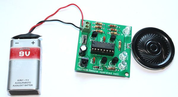
Remote operated musical bell is one of the interesting experiments every electronics hobbyist would like to make. We have made a very simple remote-operated musical bell DIY kit that requires your half an hour labor to make it work. It uses CD4017 decade counter, UM66 or BT66 musical chip and TSOP4838 infrared sensor as its…
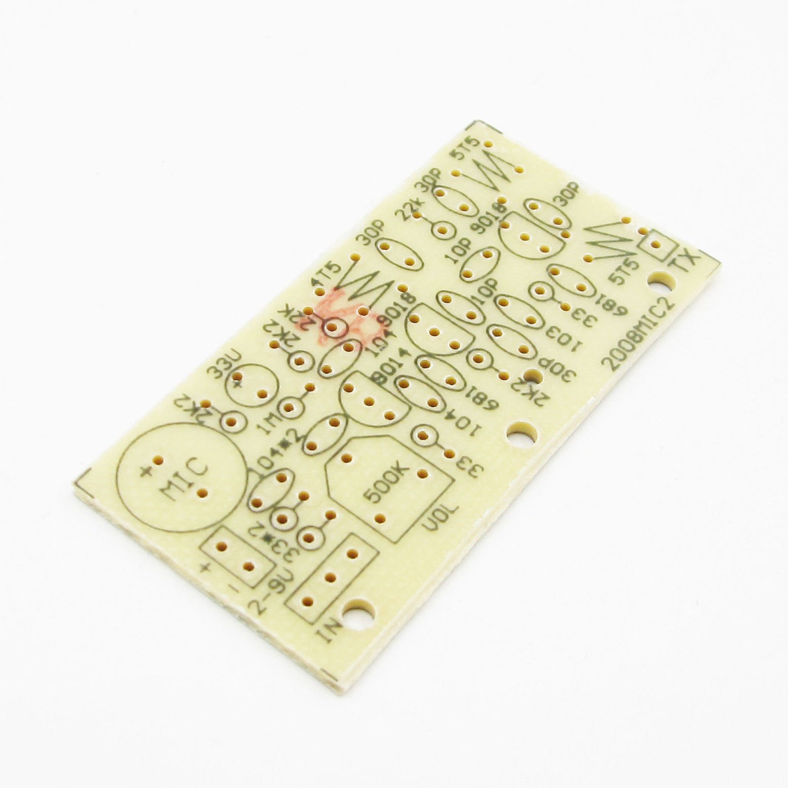
This is yet another FM transmitter DIY kit for beginners and hobbyists. It is slightly different from our previous FM transmitters. It has 3 NPN transistors and the transmission range is around 50-100 meters. It is an enhanced wireless microphone with excellent transmission quality. The voice transmitted by the microphone can be heard using an…
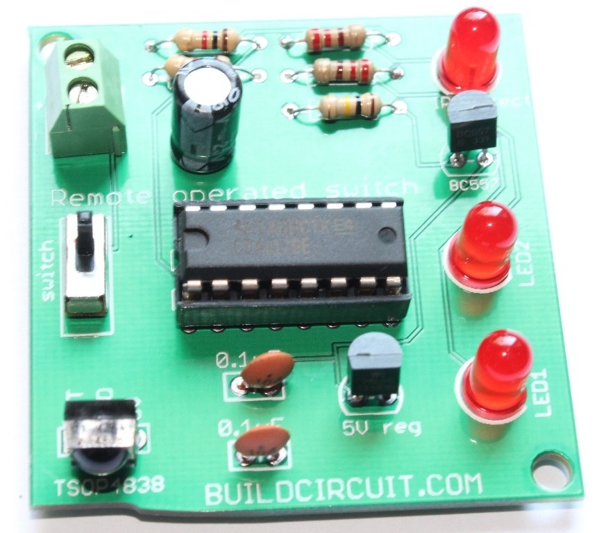
This is a simple do-it-yourself (DIY) remote operated switch. You can use this simple kit to turn ON/OFF a pair of LEDs. This has been designed basically as a learning kit. With this kit, you may learn about TSOP4838 infrared sensor and CD4017 versatile IC.
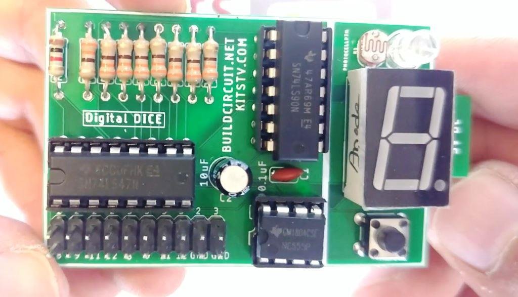
This is a different type of digital dice. We have previously seen electronic dice with 7 LEDs. In this project, we have a seven-segment display, not LEDs. When you press the tactile switch the numbers increase from 0 to 9, and when the switch is released it stops at a random number. Using the 2…
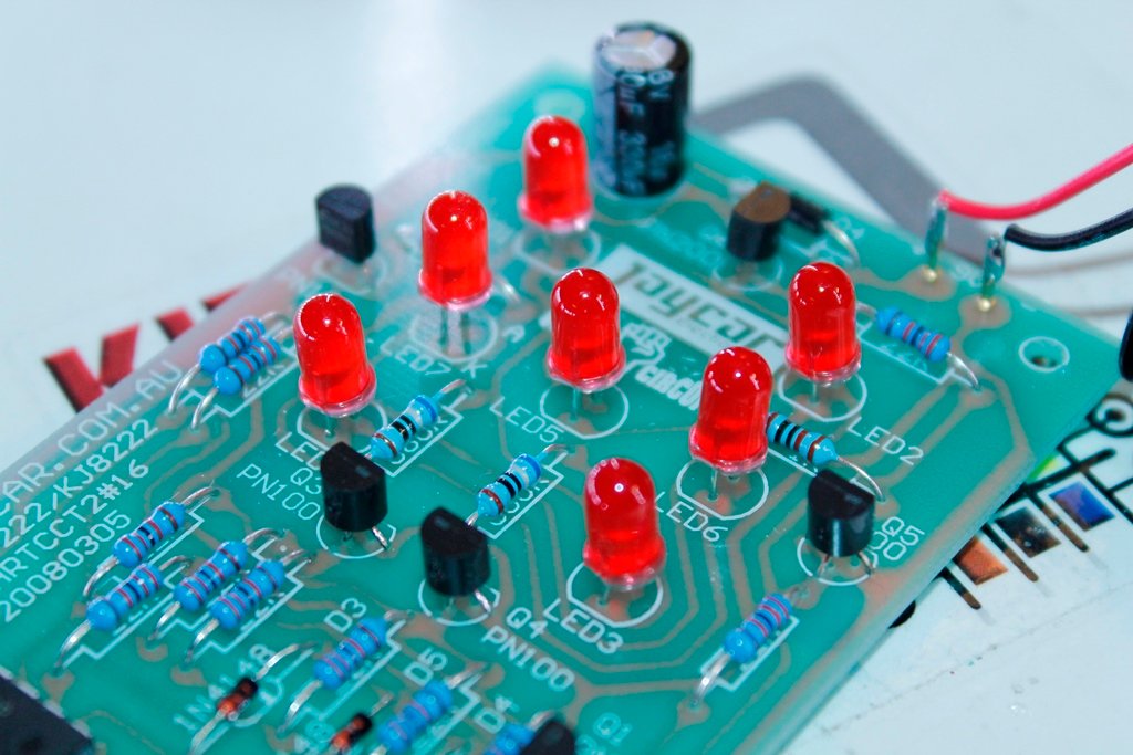
This is yet another electronic dice project from Jaycar. When you press the RED button on the PCB, all 7 LEDs flash for a while and the LEDs that stay on will represent numbers between 1 and 6. This is a basic learning kit for electronic beginners. Basic soldering skill is enough to build the…
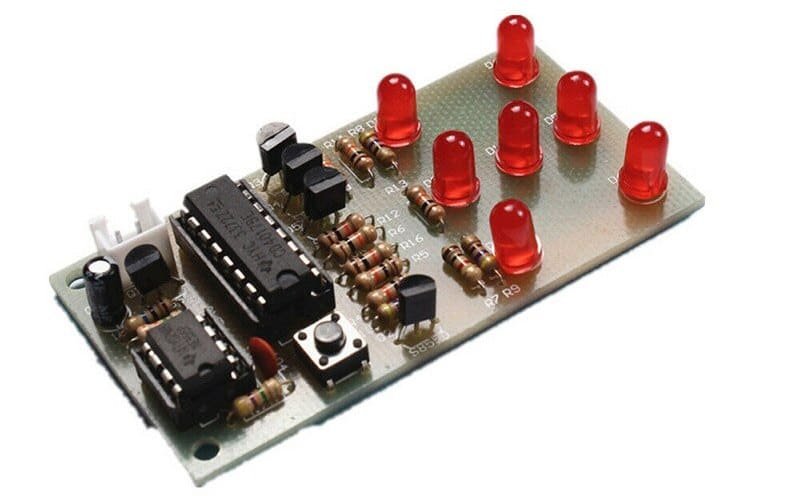
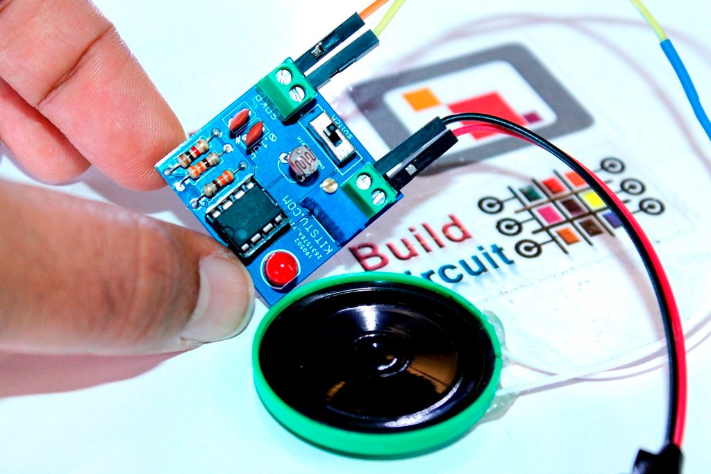
This is yet another NE555 based DIY kit for electronics beginners. A long time ago, I had published this project on this page: https://www.buildcircuit.com/sound-generator/ The electronic kit presented in this article is exactly the same circuit that I had published previously. The circuit is an astable mode timer. The output frequency of the NE555 varies…
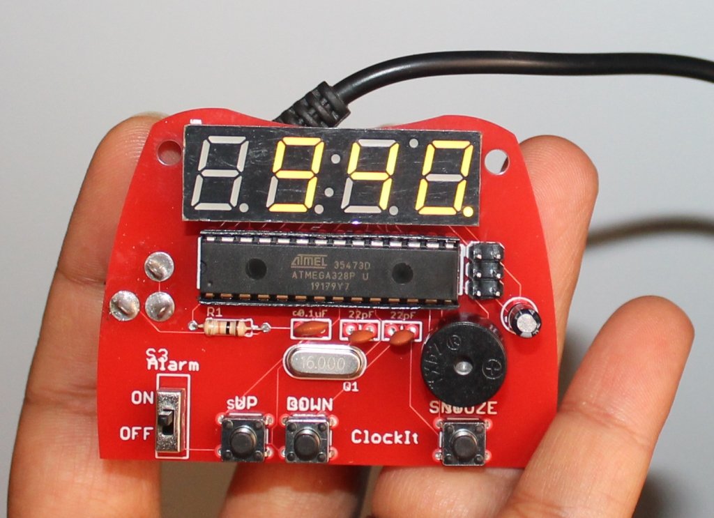
This is a great kit to learn the basics of soldering. The Sparkfun ClockIt is a basic alarm clock with buzzer based on the ever-popular ATMega328. If you’re just learning how to solder, this kit should take you 15-20 minutes. If you’re a weathered pro at soldering, this is a great relaxing build that should…
SEE ALL THE PHOTOS ON FLICKR This post shows you how to build the Amarino evaluation shield. When you buy the shield package, you will get the following components. Fully assembled kit is now available on buildcircuit.net. The PCB: PCB clearly shows the pin and component names, so, it should help you to get idea of…
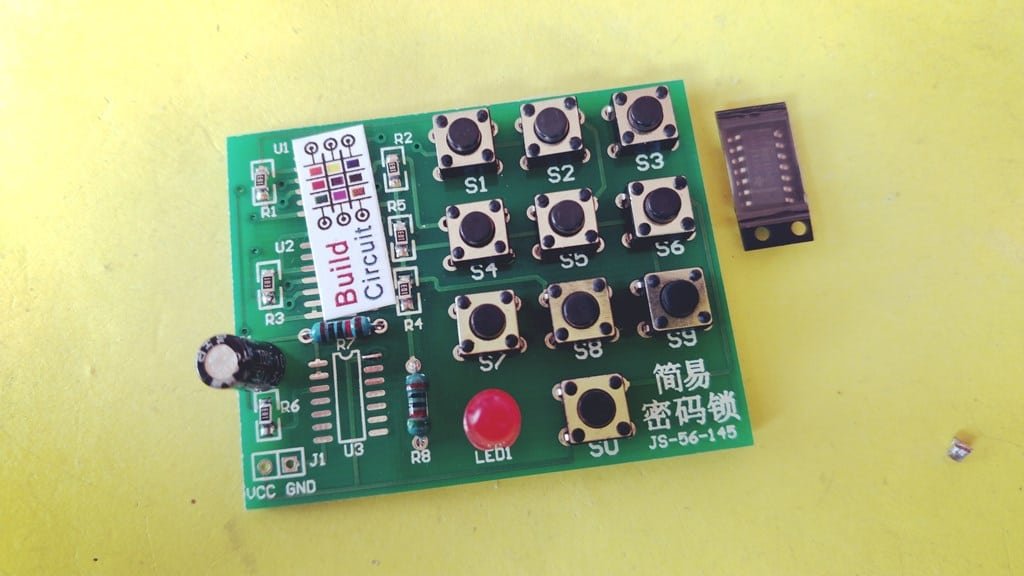
I found this small kit on Ebay. The kit is pretty easy to assemble. The following video shows the assembly steps. The kit actually turns on the LED when you press switches, 1, 4, 7, and 9. That’s it.

This is yet another TDA2030A based audio amplifier DIY kit. The kit is retired and not so popular these days. An excellent tutorial on this kit is published on this website.
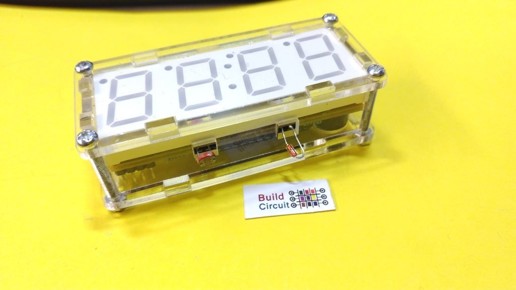
This is yet another digital clock DIY kit for electronics beginners. I have previously published several posts related to the digital clock. This kit is no different from those kits, it also displays time and the additional functions and temperature display and alarm. It also has a photoresistor which makes it sensitive to ambient light,…

This digital clock kit looks very much similar to this kit, the kit is actually slightly advanced than the previous kit. It has enough functionalities like any other regular clock. It is very accurate. It is an easy to build kit and perfect to start to develop your soldering skills. It uses the chip AT89C2051.
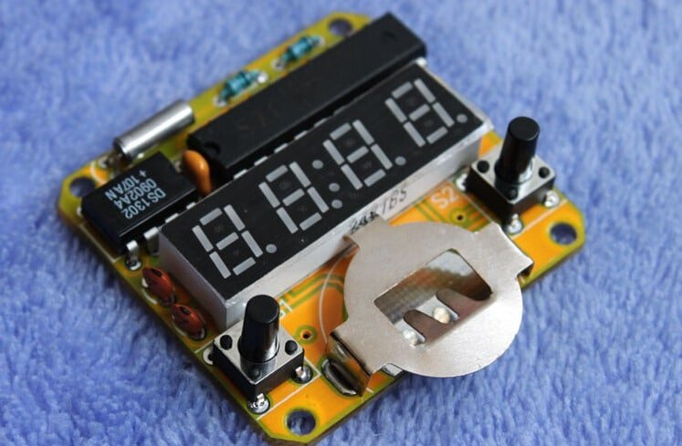
This is a simple wrist watch DIY kit for electronics hobbyists. Anyone with basic soldering experience can build the kit. This is a copy of Solder:Time watch kit from https://www.spikenzielabs.co. It uses DS1302 clock chip.

This is yet another post related to LM317. The LM317 device is an adjustable three-terminal positive-voltage regulator capable of supplying more than 1.5 A over an output-voltage range of 1.25 V to 37 V. It requires only two external resistors to set the output voltage. The device features a typical line regulation of 0.01% and…
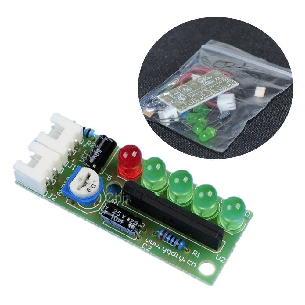
The KA2284 is a monolithic integrated circuit designed for 5-dot LED level meter drivers with a built-in rectifying amplifier. It is suitable for AC/DC level meters such as VU meters or signal meters.

This is yet another audio amplifier project. It is based on TDA2282 chip. The TDA2822M is a monolithic integrated circuit in 8 lead Minidip package. It is intended for use as dual audio power amplifier in portable cassette players and radios. Datasheet of TDA2282 You can see all the assembly images below. You can see…

This is yet another sound activated LEDs circuit. I have previously published a similar project.
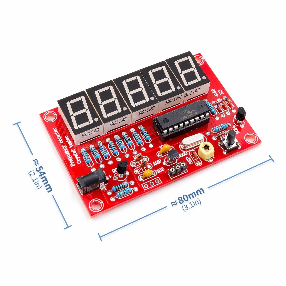
The description has been copied from manufacturer’s website. This is a PIC microcontroller-based frequency meter, subtraction frequency is set with crystal measurement functions and programmable, five digital display, easy and intuitive, all using in-line components, the circuit is simple and easy to make. Measurable frequency range: 1 Hz -50 MHz; Most commonly used to measure…