CONTACTLESS AUTOMATIC WARDROBE LED LIGHT WITH FADE EFFECT

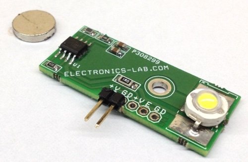
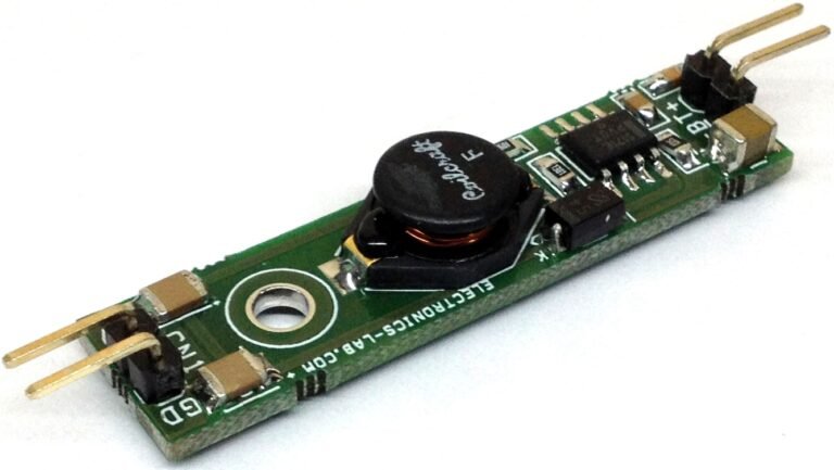
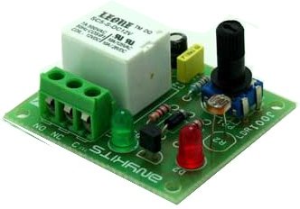
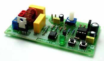
Contact-less controlled automatic wardrobe light turns on the LED when you open the wardrobe door. Τhe project is based on Hall effect IC including LED driver and tiny magnet. Board doesn’t require any mechanical switch. When magnet is close to the board, LED is off, when you open the wardrobe door magnet goes far from hall IC and its turn on the LED, the IC also has special features like soft start and soft off. This board can be used in other applications like Automotive Gloves boxes and Storage, task lighting, automotive vanity mirrors.  The APS13568 is the heart of the project. The IC can drive LED current up to 150mA. I have set the current 100mA approx. with help of R3. C2 is provided to set the FADE-IN/FADE-OUT time. The value of C2 can be changed as per application requirement.

The IC is an integrated circuit that combines an ultrasensitive, Omni polar, micro power Hall-effect switch with a linear programmable current regulator providing up to 150 mA to drive high brightness LEDs. The Omni polar Hall Effect switch provides contactless control of the regulated LED current, which is set by a single reference resistor R3. This highly integrated solution offers high reliability and ease of design compared to a discrete solution. The Hall-effect switch operates with either a north or a south magnetic pole. The switch output polarity can be set with an external pull down on the POL input pin. This allows the user to select whether the APS13568 switch output goes low when a magnet is present or when the magnetic field is removed. Chopper stabilization provides low switch point drift over temperature. The LED is turned on when the EN input goes low. This active low input can be connected directly to the Hall switch output, SO, to turn the LED on when the switch output goes low. This flexible solution allows the user to connect additional slave switches, LED drivers, PWM, or microprocessor inputs to control when the LED is on. Optionally, an external capacitor can be used to adjust the fade-in/fade-out feature. On-board protection for shorts to ground and thermal overload prevents damage to the APS13568 and LED string by limiting the regulated current until the short is removed and/or the chip temperature has reduced below the thermal threshold. The integrated Hall-effect switch in the APS13568 is an Omni polar switch. The output switches when a magnetic field perpendicular to the Hall sensor exceeds the operate point threshold, BOPx (B > BOPS or B < BOPN). When magnetic field is reduced below the release point, BRPx (B < BRPS or B > BRPN), the device output goes to the other state. The output transistor is capable of sinking current up to the short-circuit current limit, IOM, which ranges from 30 to 60 mA. The difference in the magnetic operates and release points are the hysteresis, BHYS, of the device. This built-in hysteresis allows clean switching of the output even in the presence of external mechanical vibration and electrical noise. Removal of the magnetic field results in an output state consistent with B < BRPx. Since the output state polarity relative to the magnetic thresholds is user-selectable via the POL pin, reference Table 1 to determine the expected output state.

Note: The board has omnidirectional Hall sensor. Default it set to switch on the LED in absence of magnetic field or magnet is not around, it will switch off the LED when magnet is close to the hall sensor IC or in presence of magnetic field. Remove POL Resistor R4 for reverse operation.

FEATURES

  • Supply 12V DC ( 7-24V Supply Possible)
  • LED Current 100mA (LED Current can be set to 150mA with help of R3)
  • Selectable Output Polarity
  • FADE-IN/FADE-OUT ( Soft On/Off)
  • Built In Short Circuit Protection, Thermal Protection, Reverse Battery and Load Dump Protection

SCHEMATIC

PARTS LIST

CONNECTIONS

PHOTOS

VIDEO

PCB

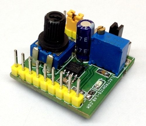
LUX METER MODULE

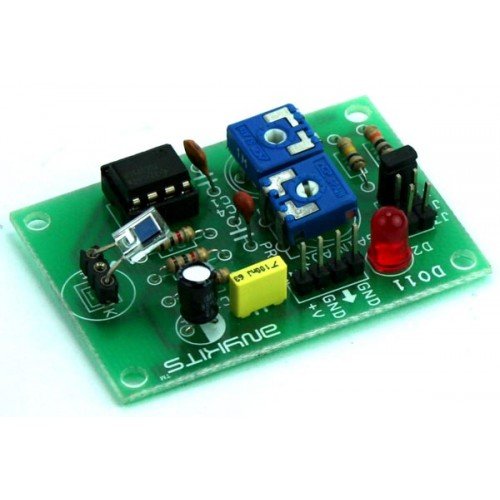
LUX Meter project has been design to measure the illumination.  Illumination is luminous flux falling on surface area of photo diode.  This illumination converted to corresponding voltage using Op-Amp circuit.

SPECIFICATIONS

  • Supply 9 VDC PP3 Battery @ 20 mA
  •  Onboard Photo Diode
  •  Onboard preset for calibration
  •  Range selection via jumper 10mV/LUX, 1mV/LUX, 0.1mV/LUX
  •  Interfacing is via berg connector
  •  Power-On LED indicator
  •  Four mounting holes of 3.2 mm each
  •  PCB dimensions 53 mm x 38 mm

The project is designed around Texas instrument Op-Amp TLC271 which can operate from single supply with low bias current, here op-amp act as current to voltage converter.  5000 LUX (approx) can be measure with a voltmeter having 5V range.  Meter is not provided.

CALIBRATION

  • J1 Jumper : 10mV/Lux
  • J2 Jumper : 1mV/Lux
  • J3 Jumper : 0.1mV/LUX
  • PR2 Preset : To Calibrate the meter
  • PR1 Preset : Fine Gain adjustment for 10mV/Lux
  • CN1 Connector : Supply 9 VDC (PP3 9V DC Battery Ideal) and Output Voltage
  • D2 LED : Power Indicator
  • D1 LED : Photo Diode (Sensor)

Standard incandescent 100W lamp should be used for approximation calibration.  To make Calibration select the 1mV/Lux J2 Jumper, move the preset full in CCW.  Connect the accurate voltmeter having range of 5V. Adjust the distance between the photo diode and Lamp so that voltmeter reads 0.38V0.  At this point, illumination on photodiode surface is about 100 Lux (aprox).  And then adjust the PR2 so that voltmeter reads 1V.  Calibration has now been complete. This project is based on Hamamatsu Photo Diode Application

SCHEMATIC

LUX_METER_SCH

PARTS LIST

LUX_METER_BOM


PCB

DOWNLOADS

SOUND ACTIVATED SWITCH – RELAY

This project is a sound-activated switch.

DESCRIPTION

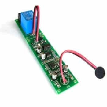
Clap switch/Sound-activated switch designed around op-amp, flip-flop, and popular 555 IC. Switch avoids false triggering by using a 2-clap sound. Clapping sound is received by a microphone, the microphone changes the sound wave to an electrical wave which is further amplified by the op-amp.

555 timer IC acts as a mono-stable multi-vibrator then flip-flop changes the state of the output relay on every two-clap sound. This can be used to turn ON/OFF lights and fans. The circuit activates upon a two-clap sound and stays activated until another sound triggers the circuit.

Specifications:

  • Supply 12V DC @ 60mA
  • On board preset to set the sensitivity
  • On board LED to indicate the Relay on/off state
  • On board Microphone
  • Relay switch 5Amps, 110V-230V

SCHEMATIC

Sound_Activated_Switch_Top_schematic

PARTS LIST

image description

PCB

PIR SENSOR

This project is an automatic PIR sensor.

DESCRIPTION

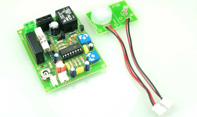
Project is based on Holtek’s IC HT7610A, which is a CMOS LSI chip designed for use in automatic PIR lamp, flash or buzzer control. It can operate in 3-wire configuration for relay applications.  In our project we have used relay instead of Traic to connect any kind of load in output, HT7610B IC is suitable for traic and HT7610A for Relay application. The chip is equipped with operational amplifiers, a comparator, timer, a zero crossing detector, control circuit, a voltage regulator, a system oscillator, and an output timing oscillator.

Its PIR sensor detects infrared power variations induced by the motion of a human body and transforms it to a voltage variation. If the PIR output voltage variation conforms to the criteria (refer to the functional description), the lamp is turned on with an adjustable duration. The circuit doesn’t required step down transformer and can work directly by applying 110V AC or 220V AC (Capacitor C7 needs to change for 220V AC (0.33uF/275V) and 110V AC (0.68uF/275V)

FEATURES:

– Supply Input 110V or 220V AC ( Capacitor Value needs to Change)
– No Step Down transformer required
– IC Operating voltage: 5V~12V
– Load Current 80mA when relay is on.
– Standby current of the IC: 100uA
– On-chip regulator
– Adjustable output duration
– 40 second warm-up
– ON/AUTO/OFF selectable by MODE pin
– Override function
– Auto-reset if the ZC signal disappears over 3 seconds
– On Board Relay to connect output Buzzer or Flash
– On Board LDR to Detect Day/Night operation
– J1 to Set the Mode
– PR1 to set the Sensitivity of the sensor
– PR2 to set the output Turn On Duration
– CDS R11 for Auto Day/Night detection
– (HIGH Voltage On Board) Do Not touch the PCB while power is on.

SCHEMATIC

image description

Mode (Jumper J1):

This project offers three operating modes (ON, AUTO, OFF) which can be set through the MODE pin. While the chip is working in the AUTO mode the user can override it and switch to the TEST mode or manual ON mode, or return to the AUTO mode by switching the power switch. J1 Jumper is to set the desired modes.

J1 Jumper Operating Mode Description
VDD ON Output is always On: Output is high RELAY ON
VSS OFF Output is Always Off: Output is low RELAY OFF
Open Open Outputs remain in the off state until activated by a valid PIR input trigger signal. When working in the AUTO
mode, the chip allows override control by switching the ZC signal.

CDS-LDR (Light Dependent Resistor):

CDS is a CMOS Schmitt Trigger input structure. It is used to distinguish between day time and night time. When the input voltage of CDS is high the PIR input is enabled. On the other hand, when CDS is low the PIR input is disabled. The input disable to enable debounce time is 5 seconds. Connect this pin to VDD when this function is not used. The CDS input is ignored when the output is active.

LDR Operations

CDS PIN  (LDR) Status PIR
Low Day Time Disabled
High Night Time Enabled

LDR Operations

OSCD is an output timing oscillator input pin. It is connected to an external RC to obtain the desired output turn-on duration. Variable output turn-on durations can be achieved by adjusting variable resistor or setting various values of RC.

Power-on Initial

The PIR signal amplifier requires a warm up period after power-on. The input should be disabled during this period. In the AUTO mode within the first 10 seconds of power-on initialization, the circuit allows override control to enter the test mode. After 40 seconds of the initial time the chip allows override control between ON and AUTO. It will remain in the warm up period if the total initial time has not elapsed after returning to AUTO. In case that the ZC signal disappears for more than 3 seconds, the chip will restart the initialization operation. However, the restart initial time is always 40 seconds and cannot be extended by adding CRST to the RST pin as shown in the circuit.

The HT7610A offers mask options to select the output flash (3 times) when changing the operating mode. The output will flash 3 times at a 1Hz rate each time it changes from AUTO to another mode and flash 3 times at a 2Hz rate when it returns to the AUTO mode. However the output will not flash if the mode is changed by switching the MODE switch. Options for effective override: Once or twice Off/On operation of power switch within 3 seconds. Options for output flash to indicate effective override operation. Flash for the circuit.

Test mode control

Within 10 seconds after power-on, effective ZC switching will force the chip to enter the test mode. During the test mode, the outputs will be active for duration of 2 seconds each time a valid PIR trigger Signal is received. If a time interval exceeds 32 seconds without a valid trigger input, the chip will automatically enter the AUTO mode

Note:
– The output is activated if the trigger signal conforms to the following criteria:
– More than 3 triggers within 2 seconds
– A trigger signal sustain duration
– 0.34 seconds >/2 trigger signals within 2 seconds with one of the trigger signal sustain 0.16 seconds.
– The effective comparator output width is selected to be 24ms.
– The output duration is set by an external RC that is connected to the OSCD pin

Override control

When the chip is working in an AUTO mode (MODE=open), the output is activated by a valid PIR trigger signal and the output active duration is controlled by an OSCD oscillating period. The lamp can be switched always to ON from the AUTO mode by either switching the MODE pin to VDD or switching the ZC signal by an OFF/ON operation of the power switch (OFF/ON once or twice within 3 seconds by mask option). The term override refers to the change of operating mode by switching the power switch. The chip can be toggled from ON to AUTO by an override operation. If the chip is overridden to ON and there is no further override operation, it will automatically return to AUTO after an internal preset ON time duration has elapsed.

This override ON time duration is 8 hours. The chip provides a mask option to determine the output flash times (3 times) when changing the operating mode. It will flash 3 times at a 1Hz rate each time the chip changes from an AUTO mode to another mode or flash 3 times at a 2Hz rate when returning to the AUTO mode. But if the AUTO mode is changed by switching the MODE switch it will not flash.

PARTS LIST

BOM

PCB

AUDIO VU METER 9 LEDS

5 LED VU Meter kit is based on LB1409 IC from SANYO, which will indicates the volume level of the audio signal it senses

  • SUPPLY 12V DC @ 50mA
  • PR1 REF SET
  • PR2 AUDIO LEVEL SET

SCHEMATIC

schematicPARTS

parts


PCB

DOWNLOADS

4 CHANNEL INFRARED REMOTE RELAYS

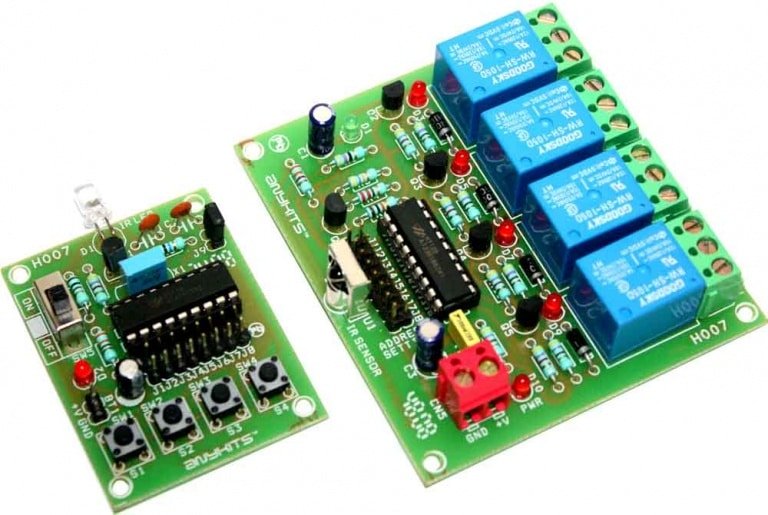
4 Channel Infrared (IR) Remote controller is using  HT12A and HT12D encoder/decoder chips from Holtek.

FEATURES

  • Supply – Transmitter : 3 to 5 VDC, 5 V @ 20 mA & Receiver : 5 VDC @ 200 mA
  • Output: 4 channel Latch or Momentary onboard Jumper for selection
  • Crystal based oscillator for the reliability of operation
  • Jumper selectable 8-bit address code
  • LED output to indicate reception
  • On/Off slide switch in the transmitter
  • Power-On LED indicator in the Receiver / Transmitter
  • Valid transmission indicator
  • 4 LED for Relay On/Off status
  • Four mounting holes of 3.2 mm each
  • PCB dimensions – Transmitter : 43 mm x 56 mm & Receiver : 80 mm x 73 mm

SCHEMATIC


PARTS LIST

Receiver BOM


Transmitter BOM

VIDEO

PCB

TOGGLE ON / OFF SWITCH

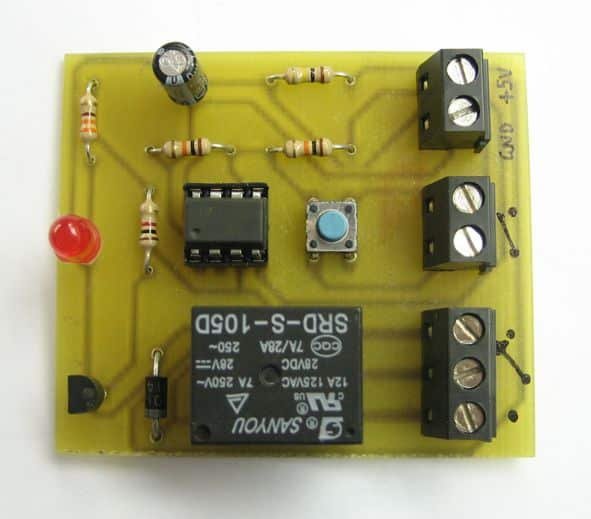
This project describes how to build a “soft touch” switch. By “soft touch” we mean that you have to push once to set device ON and push again to set device OFF. This kind of switch works by latching a relay to ON state with push of a button and with another push latch is released. It is working like flip-flop states. In that way, you can control power to a device using one push button.

The circuit is build around a 555 timer configured in a way that let it latch on one state and an action is required to change state. The circuit is powered from +5V and there are connectors to connect controlling device. Inspiration from this project and circuit is found here: http://todbot.com/blog . We added a relay on output, an indicator led as well as connectors for power, an external push button and relay contacts.

SCHEMATIC

Schematic
The Schematic for this circuit can be seen above. The circuit toggles a relay when button S1 is pressed. Operation of this circuit is simple. Pins 6 and 2 of 555 timer are at half power voltage. When output pin 3 is high then capacitor C1 is charged and when it’s low capacitor is discharged. When button is pressed capacitor voltage appears on pin 6 and 2 and output pin 3 changes state as well as capacitor voltage changes. So when output is high capacitor has +5V. When we press the button pin 3 goes low and capacitor goes 0V, when we press button again output goes high again, so we have toggle functionality. When output is high transistor T1 is conducting current and relay is latched, when low relay is released. Diode D1 is used to protect transistor from back voltage generated when relay goes off.

A disadvantage of this circuit is that when we connect power to the circuit relay is engaged. A solution to this can be found on the second reference website below.

PHOTOS

Photo_2
Circuit is in OFF state
Photo_3
Push button is pressed and circuit goes to ON state. Relay switch on a high power LED

PCB

PCB of Toggle ON/OFF Switch

REFERENCES

PCB

8 CHANNEL RELAY BOARD

This project is a general-purpose 8 Channel Relay Board.

DESCRIPTION

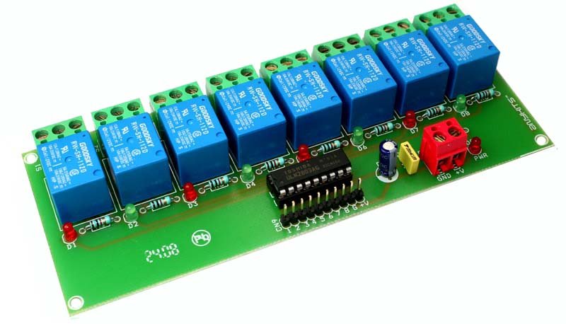
8 Channel Relay Board is a simple and convenient way to interface 8 relays for switching application in your project. Input voltage level support TTL as well as CMOS. Easy interface with Microcontrollers based projects and analog circuits.

SPECIFICATIONS:

  • Input supply 12 VDC @ 336 mA
  • Output eight SPDT relay
  • Relay specification 5 A @ 230 VAC
  • Trigger level 2 ~ 15 VDC
  • Header connector for connecting power and trigger voltage
  • LED on each channel indicates relay status
  • Screw terminal connector for easy relay output and aux power connection
  • Four mounting holes of 3.2 mm each
  • PCB dimensions 152 mm x 60 mm

SCHEMATIC

8_Channel_Relay_Schematic

PARTS LIST

8_Channel_Relay_Bom

PCB

ELECTRONIC TOGGLE SWITCH

The Project works as electronic toggle switch.

DESCRIPTION

The circuit is based on CMOS CD4013 Flip Flop IC, The circuit has two stable states, ON and OFF. Once it is ON, it remains ON till you press the switch again. A short button press of a tactile switch SW1 latches the circuit ON and another toggles it back OFF.

Relay switch contacts can handle high AC Voltage as well as High DC current, this makes the project suitable for application like ON/OFF Fan, Light, TV, Pump, DC Motor, any electronic project required electronic toggle operations and few other devices work on AC voltage up to 250V AC or DC current up to 5Amps.

Applications: TV, Audio Equipments, Radio, Fan, Pump, DC Motor, Electronic Projects ON/OFF

SPECIFICATIONS

  • Supply: 12V DC
  • Current: 60mA
  • D1: Power Indicator
  • D3: Toggle State ON or OFF indicators
  • CN1: Supply Input
  • SW1: Toggle Operation

SCHEMATIC

003_Schematic

PARTS

003_Bom_th

PCB

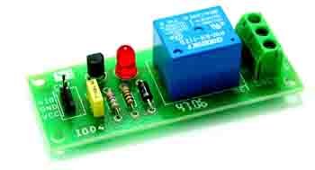
ONE CHANNEL RELAY DRIVER

This project is an one Channel Relay Driver suitable for a variety of projects.

DESCRIPTION

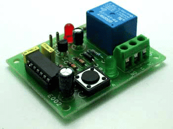
Single Channel Relay project  is a simple and convenient way to interface a relay for switching application in your project.

SPECIFICATIONS:

  • Input – 12 VDC @ 42 mA
  • Output – SPDT relay
  • Relay specification – 5 A @ 230 VAC
  • Trigger level – 2 ~ 15 VDC
  • Header pins for connecting power and trigger voltage
  • LED indicates relay status
  • Power Battery Terminal (PBT) for easy relay output connection
  • Four mounting holes of 3.2 mm each
  • PCB dimensions 27 mm x 69 mm

SCHEMATIC

ONCE_CHANNEL_RELAY_DRIVER_SCHEMATIC

PARTS LIST

ONCE_CHANNEL_RELAY_DRIVER_BOM

PCB

DC MOTOR DIRECTION CONTROLLER WITH TACT SWITCHES

DC Motor Direction Control project offers direction control using digital logic gates and a DPDT relay.

FEATURES

  • Supply input 12 VDC @ 75 mA
  • Power LED
  • DC Motor Direction LED Yellow/Green
  • Relay Output: up to 7 A
  • Onboard tactile switch for direction control
  • Relay based drive design with diode protection
  • LED indicator for direction indication
  • Power-On LED indicator
  • Terminal pins and screw terminal connector for easy input / output connection
  • Four mounting holes of 3.2 mm each
  • PCB dimensions 41 mm x 81 mm

SCHEMATIC

DC_Motor_Direction_Controller_SCH

PARTS LIST

DC_Motor_Direction_Controller_BOM

PCB

DC SERVO MOTOR DRIVER

DC Servo Motor Driver kit, designed using MC33030 IC, is the fastest and low cost way of getting your DC Servo Motor up and running.

  • Input – 12 VDC
  • Output – can drive upto 1 A Load
  • Overcurrent shutdown, overvoltage shutdown
  • Programmable reference input
  • Power-On LED indicator
  • Relimate connector for interfacing the kit
  • Four mounting holes of 3.2 mm each
  • PCB dimensions 45 mm x 54 mm

SCHEMATIC

schematic (1)

PARTS

parts


PCB

UNIPOLAR 4-PHASE STEPPER MOTOR CONTROLLER

This project is a 4-phase unipolar stepper motor controller.

DESCRIPTION

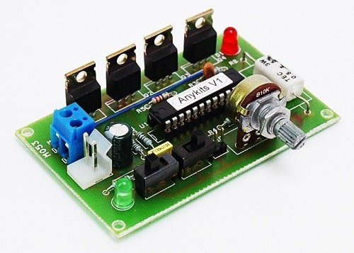
Unipolar 4-Phase Stepper Motor Controller Board will help you control a Stepper Motor or 4 individual Solenoids. This circuit consisting of transistors that serve as current amplifier and also diode to prevent damaging back EMF, circuit uses Darlington transistors to provide high current capacity to unipolar stepper motor. Just provide sequence of pulse using Micro-Controller or descript circuit to roll out the unipolar motor. On board High Watt resistor to control the current, value of the resistor can be set as per your load current requirement.

SPECIFICATIONS

  • Box Header (IDC) connector provides for easy interfacing option
  • Separate LED indicator for individual Phase
  • Screw terminal connector for easy connection of output load and power supply input
  • Power-On LED indicator
  • Four mounting holes of 3.2 mm each
  • PCB dimensions 86 mm x 49 mm

SCHEMATIC

SCHEMATIC


PARTS LIST

BOM

PHOTO

C055

PCB

RC SERVO DRIVER 0-5V

0 – 5V Servo Controller project will control a hobby type servo motor connected to it via a preset or external DC source.  This kit will be ideal add on in animatronics and motion control application.

SPECIFICATIONS

  • Microcontroller based design for greater flexibility and ease of control
  • Single Servo control via clearly marked berg connector
  • Clearly marked jumper to select signal source to control the Servo
  • Onboard preset for ready to control option for this kit
  • Power-on LED indicator
  • Diode protection for reverse polarity connection of DC supply to the PCB
  • Four mounting holes 3.2 mm each
  • PCB dimensions 45 mm x 32 mm

This is a simple but a useful circuit to control a single servo motor.  Its an ideal add on to a RC Hobbyist tool kit. The DC input to this circuit should be 5 to 6 VDC.  DC signal is given to this board at connector marked CN1 (+V and GND).   You can also feed in a variable DC signal source at the other two pins on this connector to control the servo.  To use this signal source you need to place the Jumper link at J1 in the E position.  Alternatively, you can also control the servo motor by preset PR1 mounted on the PCB.  For this you need to place the Jumper link in the I position at J1.A Servo motor is connected at connector marked CN2 on the PCB.  This connector has all the pins clearly marked for connection to the servo.LED D1 is a power on indicator ,  Diode D2 provides a reverse polarity protection for the Microcontroller.

SCHEMATIC

Servo_Driver_SCH

PARTS LIST

Servo_Driver_BOM

PCB

L293D DC MOTOR DRIVER MODULE

The project designed around L293D IC. The L293D device is quadruple high-current half-H driver. The 293D is designed to provide bidirectional drive current up to 600mA a voltage from 5V to 36V. L293D Adapter Board can be used as dual DC motor driver or bipolar stepper motor driver.  Useful in robotics application, bidirectional DC motor controller and stepper motor driver.  Separate logic supply to reduce dissipation.  L293D includes the output clamping diodes for protections.

SPECIFICATIONS

  • Motor/Logic supply 5 to 36 V
  •  Logic controls input 7 VDC max
  •  Inhibit facility/enable
  •  High Noise immunity
  •  Over temperature protection
  •  Capable of delivering output current up to 600 mA per channel
  •  The control/interface lines are accessible with Berg connector
  •  Header connector for motor and supply connection
  •  PCB dimensions 36 mm x 24 mm

SCHEMATIC

L293D_DC_Motor_Driver_SCH

PARTS LIST

L293D_DC_Motor_Driver_BOM

PCB

DC MOTOR SPEED AND DIRECTION CONTROLLER USING L293D

DC Motor Speed and direction controller project based on L293D H-Bridge and 555 Timer IC. 555 Generate PWM and L293D works as output driver. The 293D provides bidirectional drive current up to 600mA a voltage from 5V to 12V. L293D includes the output clamping diodes for protections.

SPECIFICATIONS

  •  Supply 5 to 12 V
  • Inhibit facility/enable
  • PWM Frequency 5KHz Maximum
  • High Noise immunity
  • Over temperature protection
  • Capable of delivering output current up to 600 mA per channel
  • The control/interface lines are accessible with Berg connector
  • Header connector for motor and supply connection
  • PR1 : Preset Speed Adjust
  • SW1 : 3Pin Jumper and Closer for Direction change
  • CN1 : DC Motor Supply input 5V to 12V DC
  • Dimensions  48.26mm x 36.83mm

SCHEMATIC

DC_Motor_Speed_Controller_SCH

PARTS LIST

DC_Motor_Speed_Controller

PHOTOS

DC_Motor_Speed_Controller_M047A-500x500VIDEO

PCB

HALF BRIDGE DRIVER BASED ON IR2104

This Half-bridge driver based on IR2104 gate driver IC and N channel Dpak  MOSFET  , The IR2104 is a  high voltage, high speed power MOSFET driver with independent high and low side referenced output channels. HVIC and latch immune CMOS technologies enable ruggedized monolithic construction. The logic input is compatible with standard COMOS or LSTTL output, down to 3.3V logic. A gate IR2104 driver is a power amplifier that accepts a low-power input from a controller IC and produces a high-current drive input for the gate of a high-power transistor such as a power MOSFET. In essence, a gate driver consists of a level shifter in combination with an amplifier.

This drive has many application, ranging from  DC-DC power supply for high power density and efficiency, This project simplifies the design of control systems for a wide range of motor applications such as home appliances, industrial drives, DC brushed motors , Brushless motors, fans, Tesla Coil driver, Induction coil driver, LED driver, Halogen Lamp driver.

FEATURES

  • Load Supply 12 to 36V DC
  • Load Current 10Amps (Peak 20Amps)
  • Logic Supply 12 To 15V DC
  • Input Signals 3.3V to 15V
  • SMD based tiny design
  • Required Single PWM input
  • Shutdown Input
  • Screw Terminals for Load and Load Supply
  • Header Connector for Logic supply and inputs

SCHEMATIC

Half-Bridge-Driver-SCHEMATIC

PARTS LIST

Half-Bridge-Driver-BOM

CONNECTIONS

Half-Bridge-Driver-CONNECTIONS

PHOTO

Half-Bridge-Driver-IMG_4777

PCB

AC MOTOR SPEED CONTROLLER USING U2008B

This is a low cost, current feedback phase control AC motor driver based on U2008 IC. The U2008B is designed as a phase control circuit in bipolar technology. It enables load-current detection as well as mains-compensated phase control. Motor control with load-current feedback and overload protection are preferred applications.

SPECIFICATIONS

  • Supply Input:  230V AC
  • Load: up to 500W (Triac Requires Heat sink for Higher Load)
  • Jumper J1 Selection: A-Load Current Compensation or B-Soft Start
  • PR1: Preset for Phase Control ( Ramp Current Adjustment)
  • P1 : Potentiometer Set Point

SCHEMATIC

AC-Motor-Speed-Controller-SCH

PARTS LIST

AC-Motor-Speed-Controller-BOM

PCB

PULSE GENERATOR FOR STEPPER CONTROLLER USING AD654

This stepper pulse generator project is an easy solution for stepper controller drive. It’s a very important tool and can be used to drive stepper in standalone mode.  It generates square wave pulses in frequency range 0-50Khz. This project has multiple features which are a must for stepper controller. It has on board frequency generator with wide span of frequency, Slide switch for direction control and jumper for enable or disables the stepper controller.  AD654 is heart of the project and its generate the pulse for stepper controller, output  frequency 0-50Khz, higher frequency output is possible by changing CT capacitor value connected between pin 6 and 7. Refer to data sheet of AD654 for alteration. The AD654 is a monolithic Voltage to frequency converter consisting of an input amplifier, a precision oscillator system, and a high current output stage. The board has on board LM317 regulator and have an input supply of 7-36V DC. A on board LED for power indication, PR2 trimmer potentiometer to set the frequency. PR1 is to fine tune the frequency, slide switch SW1 to change the direction of stepper motor, J1 Jumper to enable or disable the stepper controller. All outputs are TTL level. Change the R3 to 0E if stepper controller has opto-coupler input.

This Pulse Generator works along with 2.5A Bipolar Stepper Motor Driver LV8772E but not limited to.

FEATURES

  • Supply 7-36V DC
  • Frequency Output 0-50Khz (TTL Level)
  • Direction Signal TTL Level, Change R3 to 0 Ohms for direct 5V Output
  • Enable- GND or 5V
  • D1 Power LED
  • PR1 Fine Tune The Output Frequency
  • PR2 Frequency Adjust
  • SW1 Slide Switch for Direction
  • J1- Jumper for Enable or disable the stepper Controller

SCHEMATIC

PARTS LIST

CONNECTIONS

PHOTOS

VIDEO

PCB

Search for products

Back to Top
Product has been added to your cart