


Digital Object Counter using LDR and digital IC
New Project:
Easy Steps for making infrared based object counter
We need following components for making an object counter
1. 555- configured in monostable mode(automatic dark sensor using 555)
2. 555- configured in Astable mode
3. 7490- decade counter- Click here to get the datasheet
4. 7447- BCD to seven segment display- Click here to get the datasheet.
5. Seven segment display- Common Anode

Here, CC-Common Cathode and CA-Common Anode.

6. Resistors- see the schematic
7. Capacitors- see the schematic
8. Light dependent resistor (LDR)
9. LED
10. Power supply
There are basically three modules in object counter:
555 timer configured in monostable mode is a simple automatic dark sensor circuit that gives output when light falling on LDR is blocked. Pin 3 of monostable circuit has been connected to pin 4 of astable timer. When monostable circuit generates output, astable mode timer starts giving pulses to the counter module.
Frequency for counter module is set up using R4, R3 and C2.
7490 acts as a decade counter and 7447 uses the output of 7490 to display numbers on seven segment display.
This circuit counts from 0 to 9.
Click here to read about ‘How digital Clock works?’

OUTPUT: If you block light falling on LDR, the number on seven segment display will increase.

Click here to read about ‘How digital Clock works?’

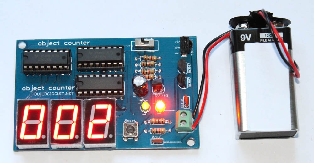
We have recently released a 3 digit digital object counter kit. You can buy the kit at BuildCircuit store.
Check out all the counters
🛠️ Dive into our collection of DIY Kits, 🔊 Audio Amplifiers, Digital Scoreboards, FM transmitters, and more!
🎶 Explore endless possibilities at our new store.


thnk u …
i want this circuit for college exibition work… i searched the for more but i can’t get now only i got it thnk u once again …
i am doing the simple project on digital logic as the object counter.
isn’t there another easy way to design the circuit for object counter using transistor,decay counter and LDR?
thank u so much for this vedio and information..this is my next project
I complete my project of object counter using resistors ,LDR,seven segment display etc.the project is very easy to understand and making methods also easy.
i connected the circuit according to the circuit diagram and although the led 1 is lighting and led 2 is blinking d 7 segment display is not working.can anyone tell me where i could have gone wrong?
You must not have not done soldering properly.Check it once more time Akshada
i did proper connections in the circuit..my led1 glows throughout the procedure..led2 blinks once at the starting..decade counter started but its not increasing the count when m blocking light from ldr.can anyone help me?
I was made this projects. My soldering is also propered. Led 2 is blinking .and led1 is lighting. There are work my project. But there are not any effect of LDR on display. .display was automatic run. . So, what i do or anything wrong in project . .say me friends please. .it’s urgent.
I was made this projects. My soldering is also propered. Led 2 is blinking .and led1 is lighting. There are work my project. But there are not any effect of LDR on display. .display was automatic run. . So, what i do or anything wrong in project . .say me friends please. .it’s urgent. . .
i want dis ckt, so than u,vry much 4 dis ckt & video…………………<3
we done the project..but without the effect of ldr the count is incrementing….
what is the rating of ldr to be used?
we done the project..but without the effect of ldr the count is incrementing…
we done the project, nd tmmrw is my presentation.. lets see wat wil happen…..
we done dis project, tmmrw is my presentation, lets see wat will happen
am on my project presently and i need more information on digital object counter system
can u send all the details ……..the circuit diagram , how to make , infrared circuit
can u help by sending this details
does anyone had solve the auto increasing 7 segment disp.????….anyone?
do reply me,if u know..Thanks in Advance.. 🙂
hey did you got the result.
i mean did u understand how to stop the increment of 7 seg
how can i add ciruitry so that it can count upto 99
guys i to hav done this ect but with out the effect of ldr the 7 segment is increasing..
please suggest me the rating of ldr to be used or this circuit is wrong?
yar am getting only odd no’s on my display what could be the problem
Perfect project !! reliable…. for those who say increment takes place without the control of LDR, place a light source near the LDR (because your LDR is less sensitive)….
Please may I consult with specialist of you that if I would like to finish a practice for running 0 to 9 digital numbers with 7 LEDs with Arduino controller and breadboard but have no the Seven segment display component. If possible, would you please kindly share the program and connection circuit dirgram for my reference to test for learning. Thank you in advance.
the project is nice but the 7 segment display is continuously counting please help me to work this project as the description given
what if the count exceeds 9 ?? there is only one segment display
can you put an additional circuit that will subtract as the motion goes the opposite way? for example a person entering will add then a person leaving will subtract, BUT on the same sensor. so you need two sensors on the same line and will just have to detect if sensor 1 is the first to get blocked that sensor two then add, or if sensor two is the first to get blocked then subtract. is that possible?