


How to make an FM transmitter
After getting several comments from young electronic students , I am rewriting this article to make the FM transmitter making process more clear.
This tutorial is for making simplest FM transmitter using one transistor. You can make this project with less components and it is an easy and simple project for beginners.
Before you proceed, please see the schematic given below. In the schematic, you will see the components required for making an FM transmitter.The transmission range of this circuit is approximately 10-20 meters.
The schematic of FM transmitter is given below:
![]()
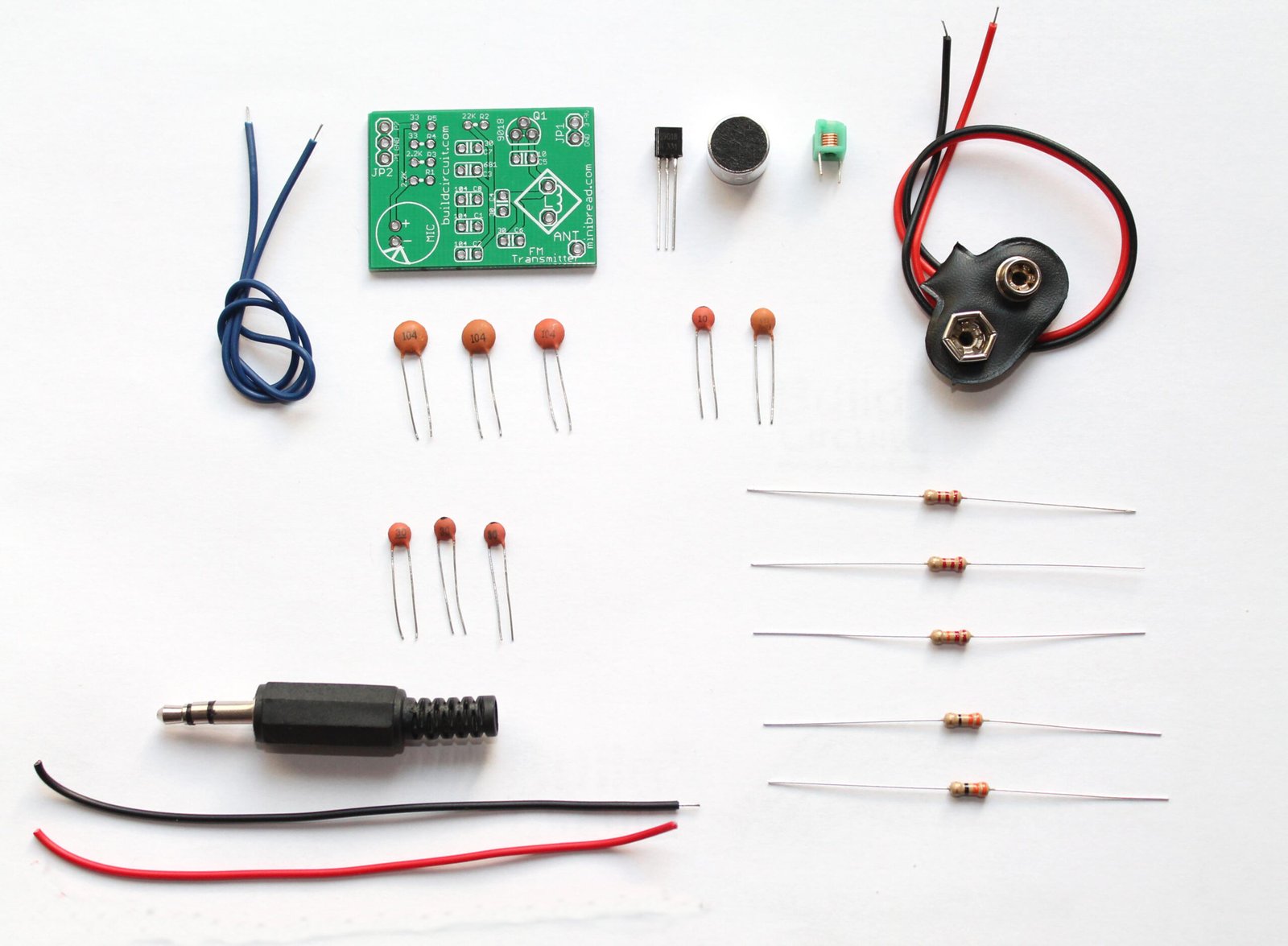
You need the following components for this experiment:
1. Q1- Transistor- 2N3904

2. Capacitors- 4.7pF, 20pF, 0.001uF, 22nF.
Note: 0.001uF has code 102 and 22nF has code 223.
3. Variable capacitor: VC1. It is also called trimmer capacitor. You can buy one from your local store. The capacitance range should be 0-100pF or 10-100pF. If you cannot get one, try to get a trimmer capacitor that has minimum capacitance of 20pF. You can also get such capacitor from your broken radio, but you may need assistance in getting that out from your radio.

4. Resistors- 4.7 kilo Ohm, 470 Ohm
5. Condensor/ Electret Microphone


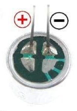
On your electret microphone, you will see that on one of the pins, there is solder pad connected to the case of microphone. Remember that pin is always negative.
6. Inductor- 0.1uF.
6-7 turns using 26 SWG wire.
You need to scrap the ends of inductor, otherwise, the inductor won’t work. Check the video given below to know how to make an inductor.
![]()
Or you can also use another inductor.
 0.1uH
0.1uH
Learn to make an inductor for FM transmitter
7. Antenna: Use 15cm to 1 meter long wire for antenna. If you have a long antenna, the signal transmission will be better.
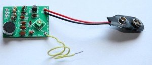
The following picture shows the components used for making FM transmitter. You can simply follow the steps shown below.
On the image shown below, you can notice that I have not used a trimmer/variable capacitor. I have used a fixed 20pF capacitor instead. So, if you don’t have a variable capacitor, you can use a fixed capacitor also.
![]()
![]()
Insert transistor, resistors and capacitors on breadboard. You can see the values of the components on the previous picture.
![]()
Then insert electret microphone.
NOTE: terminal touching the casing is -ve
![]()
![]()
Use 15cm long antenna. You can use a normal wire for antenna.
![]()
![]()
![]()
![]()
![]()
![]()
Then, with a non-conductive tool, adjust the capacitor for the clearest reception, rotate it till the receiver receives a sound from the microphone of transmitter. Use the following formula for determining the frequency.
Set your FM receiver for a clear, blank station.
Best of luck 🙂

We have made a NEW DIY FM transmitter kit. Please click here for circuit details:
 BUILDCIRCUIT HAS RELEASED A NEW DIY FM TRANSMITTER KIT. PLEASE CLICK HERE TO KNOW MORE ABOUT THE KIT.
🛠️ Dive into our collection of DIY Kits, 🔊 Audio Amplifiers, Digital Scoreboards, FM transmitters, and more!
🎶 Explore endless possibilities at our new store.


its a very good post
I copy this. Thanks
i cant found VC1 which is available in schematic diagram but not in BREADBOARD….and i also can’t see a ANTENNA clearly…
Hi, I used 20pF(right below the inductor) in place of variable capacitor. Please use any ceramic capacitor between 1-100pF. For antenna(the green wire standing erect), you can use 5-10cm normal copper wire. best of luck.
can u please tell me what is the frequency i sould tune in my receiver…..?
i made nearly three circuits…nd came to ur circuit…which is using 2n 3904..
can i replace bc 547 in that place(Q1)…? plz reply i am preparing my self for mini project..
You can use 2N3904 or BC547. Your frequency depends upon the inductor you have used or made. And on that page, you can see the formula of frequency. Please calculate it yourself. You can still try all the FM bands. The formula is http://www.buildcircuit.com/wp-content/uploads/2011/01/equationB.jpg
You can get this formula on the same tutorial page.
thanks for replying…ur really a great helper..bcoz in other blogs i can find simply many ckts but no reply..about trouble shooting…
sorry for other question…whats the range of this transmitter…?
actually i constructed the ckt in three different circuits available in internet..but all of them failed..
in receiver i can hear ..popping sound when i made to hit the mic with screw driver..but voice is not transmitting
is there any tips for troubleshoot…any suggestions for ckt…
the range of the transmitter depends upon the length of the antenna. In your case, it should be around 10cm only.
Troubleshooting:
a. Did you scrap the ends of inductor? if you don’t scrap, it doesn’t work.
b. Keep wires of microphone short. If they are long, that introduces extra inductance and the frequency changes. Therefore, keep it short.
c. Follow the instructions given on the page carefully.
d. change the value of VC1- variable capacitor, you may keep 20pF, 22pF, 33pF, keep on trying…
e. In place of R1- 470, try with 330 Ohm resistor also.
f. In place of C2- 4.7pF, insert 100pF, or 20pF or some other nearest value capacitor. but it should be in pF only.
g. Check this video: how to make inductor: http://www.youtube.com/watch?feature=player_embedded&v=UcRY_bqTTfw
h. Check this video: how to connect electret mircophone: http://www.buildcircuit.com/how-to-use-electret-microphone/
Remember that this kind of radio projects don’t work in the first attempt, you have to make several hit and trails, best of luck.
ok..thanks for troubleshooting tips….any way i am using readily available inductor…
i am going to college and use ur trouble shoot tips and post the result after that testing….
i have doubt about antenna..to use whether 15cm or 10metres..i am in middle of my mini project..
I am sorry, my mistake, it is 10cm. Not 10m, it is obvious that 10meters is too long for such a small transmitter. Did you make the length of electret microphone very short? It should be short. And do you have an extra electret microphone? sometimes, while soldering, the microphone breaks down. So, always keep extra components. I will try to make the circuit again today (just for you) and let you know if there is any problem.
sir ..plz how to use trimmer capacitor…..VC1 ….it is having three terminals….by the way i am also connecting right now…is it possible to contact u in another way..bcoz its taking long time ..to contact u sir plz…
hi bro I want to know that at how much frequency you got the output?? please tell me fast as I am in middle of my project
sir …i tried on my bread board..i made changes as u said sir..it worked..but only i can hear popping sound…in ur previous reply u said that antenna height is 10metres…!. but u have used 15 cm only that to copper wire…i have used whip antenna like the antenna used in pocket fm radios…plz reply sir i am waiting …
Hey I like the circuit and am wondering if I could integrate it with my own project. I would like to control a servo for my home made RC car. If I were to put a potentiometer in place of the mic would the signal that I receive allow me to control the speed of a motor or a servo.
Thanks
i am doing fm transmitter.
the transmitted output can be seen by mobile fm receiver.but i am not gettin the exact voice .
please tell me the exact freaquncy.
can you tell me the exact range of transmition.
how far can plase the reasever.
can i use cell phone as receiver.
Ya u can use by tuning to proper frequency.
Hello,
Great job,i have personally implemented its working propely. How can the range of frequencies be extended to say over 10meters or so,using the same circuit design with little modifications?
Regards.
Kaguai George.
Hello,
Great job,i have personally implemented its working propely. How can the range of frequencies be extended to say over 10meters or so,using the same circuit design with little modifications?
Regards.
Kaguai K George.
which wire can be used as an antenna…..how much long it should be?
use a normal copper wire, that you are using as connector on breadboard. It should be 10-15cm long.
can a wire serves as an antenna in fm transmitter…..if yes., which wire should be should be used as an antenna and how much long it should be?
use a normal copper wire, that you use as connector on breadboard. It should be 10-15cm long.
i want to make a project whih transfer electriity using wirless antenna…not using coil…..is this possible…
Not possible.
it is possible.cos i’ve seen it before on some invention site. what you are talking of is *airnergy* just google it up and confirm for yourself
inductance L1-RADIUS HOW MUCHE
there is a video on this page. just check that.
hi …friend i am confused with the trimmer capacitor , it has 3 terminals how to connect it in the circuit
hi…..friend…….i used 2 transistors bc547, bf494 instead of 2N3904 , but i am confused with the transistor terminals .emitter , base , collector……please say me whether it is ebc , ceb , ceb? For both bc547 , bf497
use multimeter to find the emiter collector base of a transistor …..!!
sitch the knob on diode symbol
can you explain how can we check a remote control usind transmitter and receiver i.e.,when a button is pressed on the remote,by seeing at the receiver end ,we should able to say which button is pressed??
what is L C in fomula of calculating frequency
l mean the value of the inductor while c the value of the capacitor
but which one capacitor pls tell me…..is used to calculating freequency in formula……
sir , please can u tell me what L&C mean in the formula for frequency please sir….
L in Inductance
C is Capacitance
f is frequency of circuit.
f=1/2Pi Underroot(L x C)
I m nt gettin the 22nf capacitor. Wht can i us instead of that??? And i have got 0.001uf capacitor of code 103 instead of 102. Will it work??????
Hey m not gettin the 22nf capacitor. Wat else can i use instead of that???? Plz. Reply…..
sir, i cant find 4.7pF can I use 5pF instead?
sir, you are doing a nice job her but i have a problem. my transmitter works only when my hand is ontop vc1. pls i need help. thanks
at which frequeny i can recive my transmitted signal
how to find frequency using the given formula
Please reply ! 🙁 need help …
What can i use instead of a Variable capacitor ?
i cant find one …. also what if i use 0.1 H Inductor instead of Copper coil. i cant find the said wire as well ! :(((
You need to have a variable capacitor to change the frequency. It will be very difficult for you otherwise to make the circuit work. And, I think 0.1H does not work. You need to have 0.1uH. see the video about how to make coil. It’s on this page.
But you yourself have used a 20pF Cap. then why need for a variable one ?
and i will use 0.1uH instead of coil and 20pF instead of variable … will it work ? :O 🙂
Yes, if you use fixed capacitor, then also it should work. But as a novice, I recommend you to use variable capacitor.
i hav’nt get trimmer capacitor. what can i do?
Then use a normal fixed ceramic capacitor between 20pF to 100pF.
Use c=20uf fix value or take out tunner frm old radio. Take simple relay switch & break it u’ll get coil.
I tried with microphone. I tried with jack wire. i didn’t find 4.7 pF and used 20 pf. I have something that has writen on it u4.7 not 4.7u is the same ting no ?
I used 1.2 uF it may be the problem?
I tried reciving fm sound with phone and radio. Didn’t work I tried every frequency.
Even I tried to calculate the frequency but I don’t know the exact valu of L …
Maybe you can tell me in what range of values (80-90 90-100) the correct frequency may be.
Thx in advice.
sir……….i couldn’t find 0.1uh inductor nor 26swg wire in my city instead 1uh is available.will the circuit still work if i use 1uh…………reply ASAP
No, 1uH does not work. You can use wire from 21SW to 30SWG. See here how to make the inductor: http://www.youtube.com/watch?feature=player_embedded&v=UcRY_bqTTfw
Now, you should do hit and trial. It may work. Make three inductors with 5 turns, 6 turns and 7 turns and try with those three. I hope it helps.
i like that project here, bt this circuit has no carrier frequency circuit so how long it can be transmitted??
the LC is the oscillator its self, a.k.a. tank circuit, it operates on a resonance frequency given by the formula. btw, i would suggest getting a frequency counter from ebay, its pretty cheap. so you can tune your fm receiver at that frequency, and you dont have to get a variable cap for that.
or you could just vary the length of your inductor to tune your transmitter.
looking at this formula:
L = [(d^2)(n^2)] / [18d + 40l]
L – in uH (inductor)
d – in inches (coil diameter)
l – coil length in inches
n – number of turns
ive been building transmitter for about 10years now. fm/pm/am/fsk/psk/etc.
Hello Sir,
Could you please explain in little detail the working of this circuit? Kindly reply!!
Excuse me, at what frequency range does this circuit transmit?
I hope you will replay.
should be 10meters.
frequency range??? in meters how is it possible
I am having simulating this circuit on multisim. Can someone please help?
i made one but i dont know the range how long does it transimt?
Sir, i would like to try to do this circuit
my doubt is how to test the signal ?? by using oscilloscope
please repay
best regards
Sir, dis is my first time of entring this site, so where can i get the component in order to practise the experiment.
You should get the components in local electronics store.
Sir Good Day.. Can I ask how far this transmitter can transmit signal??how many meters?If i wanted to extend its range of transmission, what should I adjust or what should i change?
This is my first time here..Please reply sir..Thank You!!
I probe this and this is a lot of noise , so I think we need a farady jail
what is range covered by transmitter antenna.
10 meters
sir pls tell which capacitor value will be used in calculating the freequency in formula…………….
sir pls tell me which capacitor value will be used in formula………………..
Sir, I want to send music as my modulated signal. I am actually doing this for the first time. Can I use a female 3.5mm jack and connect it to an audio source? Please help me…
i dont find 2n3904 what another transister should i use in this place
Hello ,
Dear Sagar Really You Are Nice Man and Helper :
Very Good Job :
Thankssss 🙂
can we give the input of
3.5mm jack instead of microphone?
sir,what receiver can i use? in this there is no receiver circuit..
the receiver circuit should be tuned to the same frequency know… so can u post the receiver circuit….please….
sir I used condensor mic will it work
Are there any values of variable capacitors because the shopkeeper ask me the value
The value of variable capacitor can be between 0-100pf. You can also use 20-100pF capacitor also.
Very nice and illustrated project. But I’m little unhappy with range 10 meters. Is there any shortcut way to increase it ?
sir pls tell which capacitor value will be used in calculating the freequency in formula – See more at: http://www.buildcircuit.com/simple-steps-for-making-fm-transmitter/#sthash.lYtj5LPK.dpuf
sir where you can use trimmer in transmitter circuit
i want to switch diagram about following : 5 resistance,4 capacitance, capacitor,mic, antena, transmitter, transistor, +v&-v
can i use a condensor mic
YES
It is good.i’ll make it but whats the range of it?
about 10 meters only
sir what happens if you increase the amount of coil turns
The inductance will change.
Inductance will increase if turns are iincrease or it will decrease if turns are decrease
Increases
Sir
I wand fm transmetter 2km range plez help me gave me full datel what price and were i bay.
what if you increase the number of coil turns
It will vary inductance of coil resulting in frequency change.
Hello, how can I make the same FM circuit but with changeable frequency (transmitter and receiver).
My school Cleveland Institute of Electronics expands on the FM transmitter plan a little bit. Theirs has a larger range. Here is their posted building plan from one of their instructors: http://cie-wc.edu/freekitplans.aspx
this circuits building is very simple
whats that arrow before R1
Hi, I think this would be nice for a personal project but I have a question, Can i use an earphone jack instead of a microphone so that i can transmit the signal from an mp3 player (like an iphone) to the radio? If not, can I still use this design but only changing a few thing in order to make it work with a jack instead of a microphone?
Yes you can, just connect every line from your earphone jack microphone to the microphone entrance circuit or even you can use your small speaker as a microphone if you prefer. Just remember the circuit is not stereo and you have to join the line A with B from your mp3 player or other device speaker lines you want to use as source of sound with the positive line in the entrance of your circuit.
it is nice
how can get inductor turn
do you possible if use earphone in please of mic
how to check these transmitter after completing…
please sir help me hou check after completing of these fm transmitter
Just transmit any song in it and turn your reserves frequency until you set the song which u transmit.
How can increas the efficiancy of the transmitter
Switch ön the transmitter.then in recevier(any radio) tune that till u get reception keep transmitter 10 ft away from recevier
How will you make your fm transmitter board.
nice really good post by fm transmitter circuit.
it”s really very good job.
Switch on the transmiter , We have to get a reciever to acepts the signel. Give some sound to microphone. Switch on receiver (any fm radio). Now we can her the sound in receiver.
sir i am very new to this field and i bought a new multimeter dt830d but i am not sure whether it is working so how can i test it. i havve all the above components to make a transmittor
instead of wirewound inductor you made and as shown in description instead of wirewound inductor can i use a fixed 0.1uh inductor will the circuit work. and also tell me any circuit modification to increase the range. or any other circuit.
yes u can use 0.1uh inductor in the circuit it wil works
If I replace the microphone with an audio jack would it transmit music from an MP3 player.
yeah it’ll work,..
Sir, bc547 transistor and 2N3904 are same or diffrent?
BOTH ARE SAME
I like
I visited various blogs however the audio feature for audio
songs current at this web site is actually excellent.
How you can calculate its frequency?
To calculate the frequency using given formula what is the value of C=?
Please feedback me.
Thanks
Capacitance of trimmer or fixed capacitance (20uf)
which type of inductor can we use?
which typoe of inductor can we use?
hello..sir How we make the Inductor ?
are all capacitors are ceramic? and does the negative side of the battery can be consider as a ground? help plsss thankz great post
Hi, thanks for the post! But i dont see any variable capacitor in the picture with bread board! is that VC for fun!( i’m kidding! :D)
Hi, this design has some little problems! 1st the resistor for bias mic is to low it should be 47k for 9volt supply.
C2 must be 10p couse 4.7 is to low and T2 get some problem in turning on. and must important thing is that mic shouldn’t connect directly to base use 22nf capacitor to bipos it.
Sir i made it bt it could not worked ……………
amzing its wrking for me
Hello Sir,
Is there any way to create a FM transmitter of “480 kHz”?
If yes then please help me out.
really a graet and helpfull post for me thanks
it is nice
how to receive transmitted signal?
sir please i request you answer this that to how to increase the range?
I am a Communication Engineering student from Ethiopia. Your project seems smart. but what if I want the capacity to be raised to 1000m?
Hey Melaku, i think you first need a powerful battery plus you need to adjust the length of the antenna and look for a transistor with great amplification factor.
ain’t sure coz am a computer eng. student too but hope that the best i can say.
hi, do you have any FM transmitter with 10W of power., i would like to know if know how to build? this is may contance number +639266730147
yea i have a transmitter if 10 w of power which was design by us in our final year project in our college
it is nice
how you can find inductor turn
please give instruction.&
do you possible if you can use earphone ins ted of mic
hi. can i know what should be modified if i want the transmitter to transmit for about 8000 square feet. thanxs
#haw i Ned to know hawwww ******** **
O
is there any replacement for 22nf capacitor. can i use a 22 SWG enamel wire for making inductor???
Greetings I am so glad I found your weblog,
I really found you by mistake, while I was browsing on Digg for something else, Nonetheless I am here now and would just like to say cheers for a tremendous
post and a all round thrilling blog (I also love the theme/design), I don’t have time to read it all at the moment but I have bookmarked it and also added in your RSS feeds, so when
I have time I will be back to read much more, Please do keep up
the superb jo.
i m too much benifited by this video
not to bad . 🙂
:W #$can you make it simpler$#!!!!!!!!!!!!!!!!!!!!!!!!!!!!!!!!!!!!!!!!!!!!!!!!
🙁 i no have rite parts please send reply !!!!!!!!!!! need help emale darthvaderthe1@hotmail.com
i have .22uh inductor will it work??
So my group and I decided to try to modify this project a little, by replacing the microphone with a male headphone jack, we didn’t have a new one but I used one from an old pair of headphones. It didn’t seem to be working, but when we set it near the radio we were using as a test, after removing the jack because we were not getting a signal, we began to pick up other radio signals while varying the 0-100 uF capacitor. Does anyone have an idea of why it is doing this?
I saw your circuit diagram, Your explanation is very nice, Thanks you very much. I want to make a
Thanks for brief explanation.
Can u explain the circuit operation
THIS IS VERY NICE, ANY-MAN CAN RELY ON IT
Thanks man,, is there any way of making a good antena,bcoz without antena my transmitter was giving 10 meters range,,with antena range was increasing but causing noise
worked for me. 🙂 such a friendly tutorial. thanks!!
From the formula above, if I use capacitor 20pF and inductor 0.1µH, that mean I will get frequency 112.60 MHZ, is right? Thanks.
tnx itis very good … my first attempt success … tnx
thank you sir !! given circuit work properly !!
Great job Thank you
(102) code refer to 0.1uF not to 0.001uF
Hi hameed bhai, can you recheck your ceramic data table. I think you are doing some mistake
sir how can finde the value of inductor and capacitor? it is possibl through multimeter?
how can finds the value of inductor through multimeter?
Wow, FM Transmitter :D, great..
is it work well.., with that thing?
if can’t sound maybe on calibrating freq, tuning transistor to 88-108Mhz RF
the inductance is ok, nothing usefull with that, need 3mm long to create tuning form.
Result, Not Work.. 😀 haha
hi , i am unable to found 2n1904 can i use any other transistor?
hello how do connect bettery – and + ?plz help
I have a question about the formula.
I know L is inductance, but I want to to which capacitor value to use for C.
I am not able to find the frequency.
Is the 20pf capacitor necessary?
How can I mix music or my voice through the transmitter.