


How to use 315Mhz RF transmitter and receiver modules with arduino
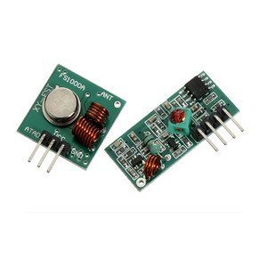
Description: This wireless transmitter and receiver pair operate at 315Mhz. They can easily fit into a breadboard and work well with microcontrollers to create a very simple wireless data link. Since these are only transmitters, they will only work communicating data one-way, you would need two pairs (of different frequencies) to act as a transmitter/receiver pair.
Note: These modules are indiscriminate and will receive a fair amount of noise. Both the transmitter and receiver work at common frequencies and don’t have IDs. Therefore, a method of filtering this noise and pairing transmitter and receiver will be necessary. The example code below shows such an example for basic operation. Please refer to the example code and links below for ways to accomplish a robust wireless data link.
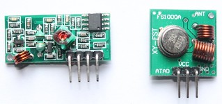
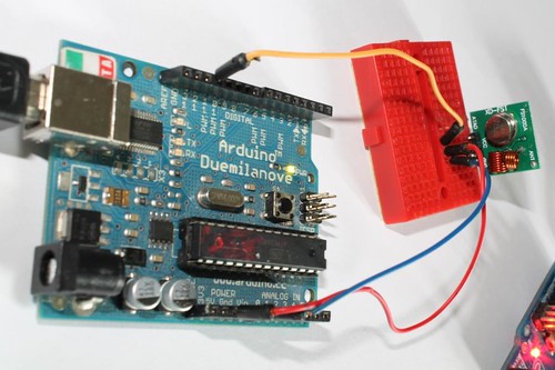
Module on the right: Transmitter
![]()
Application environment
Remote control switch, receiver module, motorcycles, automobile anti-theft products, home security products, electric doors, shutter doors, windows, remote control socket, remote control LED, remote audio remote control electric doors, garage door remote control, remote control retractable doors, remote volume gate, pan doors, remote control door opener, door closing device control system, remote control curtains, alarm host, alarm, remote control motorcycle remote control electric cars, remote control MP3.
Receiver module parameters
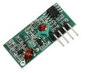
1. Product Model: MX-05V
2. Operating voltage: DC5V
3. Quiescent Current: 4mA
4. Receiving frequency:315Mhz
5. Receiver sensitivity:-105DB
6. Size: 30 * 14 * 7mm
Technical parameters of the transmitter module
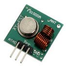
1. Product Model: MX-FS-03V
2. Launch distance :20-200 meters (different voltage, different results)
3. Operating voltage :3.5-12V
4. Dimensions: 19 * 19mm
5. Operating mode: AM
6. Transfer rate: 4KB / S
7. Transmitting power: 10mW
8. Transmitting frequency: 315Mhz
9. An external antenna: 25cm ordinary multi-core or single-core line
10. Pinout from left → right: (DATA; VCC; GND)
![]()
An example:
In this example, receiver and transmitter modules are connected separately to two Arduino boards. The transmitter data pin is connected to Pin 12 of Arduino and the receiver data pin is connected to Pin 11 of Arduino.
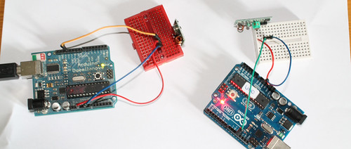
Data pin of receiver module to Pin 11 of Arduino.
Please note that there are two separate Arduinos for each module.
Connecting transmitter module to Arduino:
Sketch:
Download library(Virtual wire)
Connecting receiver module to Arduino: 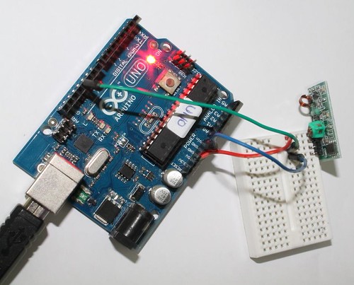 See all the images on flickr Sketch:
Download library(Virtual wire)
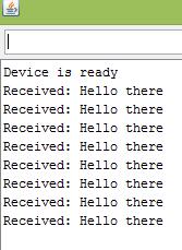
Output:
The transmitter sends a string “Hello there” and the receiver receives it and displays on serial monitor.
Related links:
1. Virtual wire- Arduino Library
2. Buy 315Mhz receiver and transmitter modules on www.buildcircuit.net
3. Video
![]()
🛠️ Dive into our collection of DIY Kits, 🔊 Audio Amplifiers, Digital Scoreboards, FM transmitters, and more!
🎶 Explore endless possibilities at our new store.

Wonderful work!!
Really helpful.
I thnk the tx ckt is in astable mode.What’s the output from pin 3?…Does it produce pulse(high/low) or it gives completely HIGH SIGNAL?
It gives high/low pulse, it is in astable mode. please check the circuit without adding the transmitter.
Hello,
Interesting stuff. I was able to test mine like this and am happy to see that it works!
What kind of antenna would you use for proper use of the module?
Is there an easy way to decode/encode the signal, or is the solution with the OpAmp good enough?
Thx!
What are the components that i would require to control a servo motor using a rf module ? Honestly , i have very low confidence in ‘ELECTRONICS’ but yes i have a background in coding.
please help me on how to apply your NOTE. tnx 🙂
NOTE: You will see a number of false triggering in the circuit because the data pin of receiver module will be giving 2-3 volts all the time. Arduino won’t be able to figure out if it is a right or wrong signal. Therefore, you will have to make a circuit or modify the code which can differentiate the desired signal from the undesired one. However, you can use this circuit to see if the transmitter is transmitting the right signal and the receiver is receiving it.
I also recommend you to use a multimeter and check the voltage level of data pin (receiver module) before and after receiving the signal. From there, you will get the idea of excluding the unwanted voltage levels.
Hint: You can use an Opamp to make a comparator to exclude the unwanted signal or modify the code in a way that it ignores 2-3 volts and takes the signals which are greater than 3 volts.
please help me , i want to apply the note you said. can you teach me how?
NOTE: You will see a number of false triggering in the circuit because the data pin of receiver module will be giving 2-3 volts all the time. Arduino won’t be able to figure out if it is a right or wrong signal. Therefore, you will have to make a circuit or modify the code which can differentiate the desired signal from the undesired one. However, you can use this circuit to see if the transmitter is transmitting the right signal and the receiver is receiving it.
I also recommend you to use a multimeter and check the voltage level of data pin (receiver module) before and after receiving the signal. From there, you will get the idea of excluding the unwanted voltage levels.
Hint: You can use an Opamp to make a comparator to exclude the unwanted signal or modify the code in a way that it ignores 2-3 volts and takes the signals which are greater than 3 volts.
That is a very good tip particularly to those new to the blogosphere.
Simple but very accurate information… Thanks for sharing this one.
A must read post!
delicious for beginers like me. thx
Do you know if its possible to use one arduino to receive and transmit data?
I’m thinking about two arduinos (both with tx and rx modules) communicating to each other.
Thanks!
Thanks for putting this online. Easy to follow and very satisfying to get working.
Now I’m looking to get my link to control separately four relays at the receiver using four switches at the transmitter.
Anyone else attempting (or successful) something similar?
Can you ditch the receiver and make a mini radio station using the transmitter and Arduino?
hi,,i’m rafles
can u explain how to use this rf module in mikrocontroller??
regards,,
I dont know why these modules always get a signal about between 2 and 3 volts in the multimeter at dc scale when we dont have nothing being sending from some tx and the when the rx module is working by between 5 and 6 volts. Anyone knows why? It is not noise in my opinion.
These devices have an automatic gain control so they can receive signals of varying strength. This means that they will try to find a gain level at which there is a ~50% duty cycle, and if there is no signal they will turn up the gain until the background noise is at that level.
You need a transmit and receive algorithm which is smart enough to differentiate between noise and a signal, and by themselves they aren’t sufficient to implement a “wireless wire”. You will want to look into VirtualWire or one of the Manchester encoding libraries out there.
Hi, Great post and very easy to follow. I tested mine and it worked really well. I am using these components with an ultrasonic Sensor HC-SR04. I can get the sensor to measure distances but cannot get the data to transmit to reciever. I am new to coding so any help you give would be appreciated the code for the ultrasonic sensor is below. Can you help me in coding……taking the distance measurement and using your code transmitting the distance output to teh reciever.
//code for testing Ultrasonic Sensor
#define ECHOPIN 3 // pin to recieve echo pulse
#define TRIGPIN 2 // Pin to recieve Trigger Pulse
void setup ()
{
Serial.begin(9600);
pinMode(ECHOPIN, INPUT);
pinMode(TRIGPIN, OUTPUT);
}
void loop ()
{
// Start Ranging – Generating a trigger of 10us burst
digitalWrite(TRIGPIN, LOW);
delayMicroseconds(2);
digitalWrite(TRIGPIN, HIGH);
delayMicroseconds(10);
digitalWrite(TRIGPIN,LOW);
//Distance Calculation
float distance = pulseIn(ECHOPIN, HIGH);
distance= distance/58;
Serial.print(distance);
Serial.println(” cm”);
delay(200);
}
Hi, Declan.
The HC-SR04 works by sending 8 pulses of 40 kHz sound immediately after receiving a 10 micro seconds high trigger; then, immediately after sending these 8 pulses, it starts collecting the echo, which is the data sent back to the Arduino.
It does all this automatically, and it is not programmable: you cannot send data through it.
I have several transmitters, that is, remotes for another device. I assume the receiver will see the remotes, but can it be made to work only with certain codes? In other words I think my receiver send out a code and I’d like to screen out other remotes.
I just bought an Rf transmitter an receiver just like those one above. My goal is to open a light trough rf. What do I have to do? Can I do it only with those RF chip or should I have to buy arduino to make it work?
Now I’ve tried many pinout possibility but I cant make it work
Thanks
Lower Range Problem when using 315 and 433 Tx-Rx as Pair for two way communication…
Only getting apprx. 1 cm range .. What to do for higher range of nearly 50+ meters now..
Lower range Problem when using 433 and 315 as Transmitter-receiver pair.. getting only 1cm range … what steps for higher range..?
Works perfect!
Thanks a lot,
Very nice! Can I send the file using the 433 MHz wireless system? I think as an image.
Hi, I’m doing a project on locating parked vehicle using RF module and arduino. Can you help me on coding?
Thank you for the instructions
I made my RF project using different instructions I found on the net.
I have an outdoor unit with a DHT22 thermometer and the transmitter unit and an indoor unit with a receiver, a real time clock and an LCD display and I send the measured temperature and humidity values through the RF transmitter to the indoor unit and show them on the LDC. Usually it works properly.
But after a certain time the received string starts to be shorter and I loss first some chars from the humidity value later the whole humidity and some chars from the temperature also. During this I am monitoring the the sent string through the serial monitor and it is correct.
Have you ever detected this issue? Do you have any suggestion / solution to do it?
THX, Gyalu
Hi, I wish to control wireless on/off function for an electrical board that needs 9V-12V power.
I have 2 channel (12DC), RF remote kit, but I don’t know how, to connect them.
Kindly someone help me.
I can connect only battery, I understand only -/+ connection, but what is A,B and C. Where those have to be connected, I do not know.
great article …
I need help
I am designing a distance meter, but for that I will use (read) the signal strength value (the RSSI technique) sent by TX. I will can do with this RX and TX?
can we use rf transmitters to transmitt its existance to rf reciever.. fyi.. i need many transmitter to respond to one reciver.. with each of them having different address.
Hello..
thanks for your article.
can i use KXDJS2002.1(RX) & FSI000A(TX) with UNO board???
Your sketch is very good.
but i have one question. in the sketch, there are any information about pin 12 and & pin 11.
when i want to change the rx/tx pin, what do i have to do?
No matter what I do the receiver won’t work. This is the 2nd receiver I’ve bought and for some reason it doesn’t want to read and output the data to the serial monitor. I’ve followed the tutorial by the letter and still nothing. Anyone have any suggestions?
Thanks guys