


Digital object counter DIY kit

This kit is based on my previous tutorial on ‘digital object counter‘. I had published the tutorial under ‘minibread’ category. Please check the tutorial.
In that tutorial, you can see that there is only one seven segment display and there is no reset switch. Well, that was extremely basic circuit.
What’s new?

My new DIY digital object counter works with TSOP4838 infrared receiver and there are two seven segment displays displaying numbers from 0 to 99. An IR transmitter is oriented towards the TSOP4838 infrared receiver of counter module and objects are moved between the counter and transmitter modules. Each time an object passes between the two modules, the seven segment displays show increment in numbers. The counter module can be reset to 0 at any time and restart the counting.

Watch the video below:
The counter can be reset to 0 by pressing the reset switch(see on video). The counter stops counting if the IR rays is continuously falling on the IR sensor. As soon as an object obstructs the IR signal, the counter immediately counts the interruption.
The distance between the counter module and the IR transmitter should be around 1 meter.
The module can also be tested with general remote control. Thus, you can also call it as a simple remote tester. For each press on your remote control, there is increment in number.
Power supply: The counter works with a 9V battery and the IR transmitter works from 6V to 9V.
Counter operating with a remote control:
Schematic of counter module:
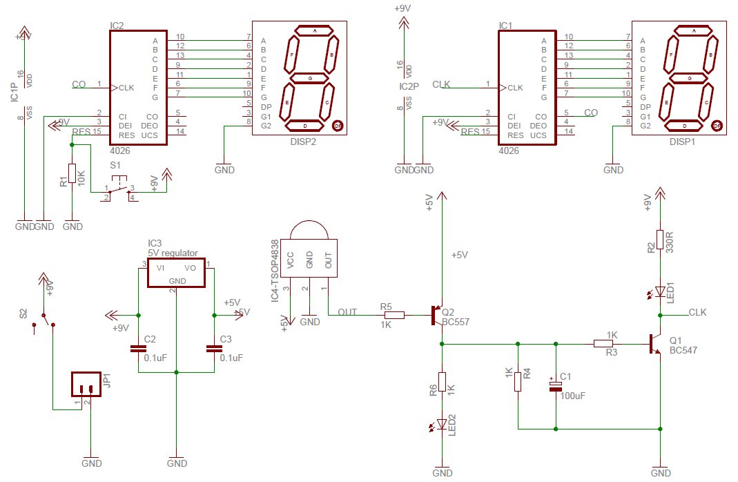
When TSOP4838 infrared receiver receives infrared signal, it triggers BC557 and switches on LED2. This trigger also charges the RC circuit network made up of C1(100uF), R3(1K) and R4(1K) and switches on the transistor BC547 for a few seconds. Transistor Q1 switches on the LED1 and gives clock signal to IC1(CD4026). For each clock, CD4026 drives the seven segment display and increases the numbers on the display.
Pin number 5 of IC1 is connected to pin 1 of IC2 for chaining the two CD4026 chips. For adding one more digit, the pin 5 of IC2 should be connected to pin 1 of IC3.
Schematic of IR transmitter module:

GO TO IR TRANSMITTER ASSEMBLY INSTRUCTIONS PAGE
IR transmitter is based on astable mode of 555 timer. The 555 timer, resistors and capacitor on the transmitter module output IR rays at 37.974Khz(approximately 38Khz). The TSOP4838 infrared module operates at 38KHz infrared frequency, however, that is not so strict with these kinds of basic experiments. It actually operates at frequencies between 30Khz to 40Khz.
Use astable mode frequency calculator for finding out the frequency of 555 timer. While using the online calculator, enter R1=18K, R2=10K and C1= 0.001uF, you will get 37.974 KHz.
How to use the kit
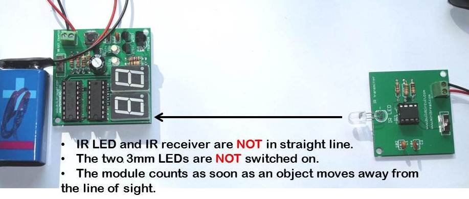
Place the two kits facing each other in a straight line. The IR receiver(on the counter module) and the IR LED(on the transmitter module) can be kept in a line of sight(straight line). When you move an object in between the two kits, the counter module counts the number of interruptions in the line of sight.
Behavior 1: When you place the IR receiver and the IR LED in a straight line, the two 3mm LEDs on the counter module are switched on and it counts as soon as there is an object in the line of sight.

Behavior 2: When you place the IR receiver and the IR LED close to each other but not in a straight line, the two 3mm LEDs on the counter module are switched off and the counter counts as soon as an object moves away from the line of sight.
Please watch the following video to be more clear:
Other related tutorials:
🛠️ Dive into our collection of DIY Kits, 🔊 Audio Amplifiers, Digital Scoreboards, FM transmitters, and more!
🎶 Explore endless possibilities at our new store.


Kul
hi sir….can i ask favor. can you please send me all the material use in this digital object counter and its lining?please….
thats cool, can you help me, i have a coin operated pc..and i want to have a digital coin counter inside the box, it has a sensor facing each other once there is an interruption it will trigger the relay to close and thats it, it will give a time for the user…how can i connect a counter on its existing sensor so that i dont have to build another sensor for the counter…thanks
sir i hane to make an eye blink counter using this principle. i need your help in this regard
Very interested in this product. However, I need the digits to be displayed about 1m away from where the IR sensors would be located. Is this possible, how could you kit be modified to accommodate this
Ryan
How do I build a one sided digital counter? Meaning the transmitter and reciever can not be across from each other.
Can you please mail me the .sch and .brd file to akhilsajeev4242@gmail.com.
do you have digital counter for measurement? and how is it if it is already assembled? please reply. .thanks.
I bought one and assembled it as described on the website but unfortunately it does not work .