
Assembly Tutorial- 3 Digits – Digital object counter DIY kit
🛠️ Dive into our collection of DIY Kits, 🔊 Audio Amplifiers, Digital Scoreboards, FM transmitters, and more! 🎶 Explore endless possibilities at our new store.
🛠️ Dive into our collection of DIY Kits, 🔊 Audio Amplifiers, Digital Scoreboards, FM transmitters, and more!
🎶 Explore endless possibilities at our new store.

🛠️ Dive into our collection of DIY Kits, 🔊 Audio Amplifiers, Digital Scoreboards, FM transmitters, and more! 🎶 Explore endless possibilities at our new store.
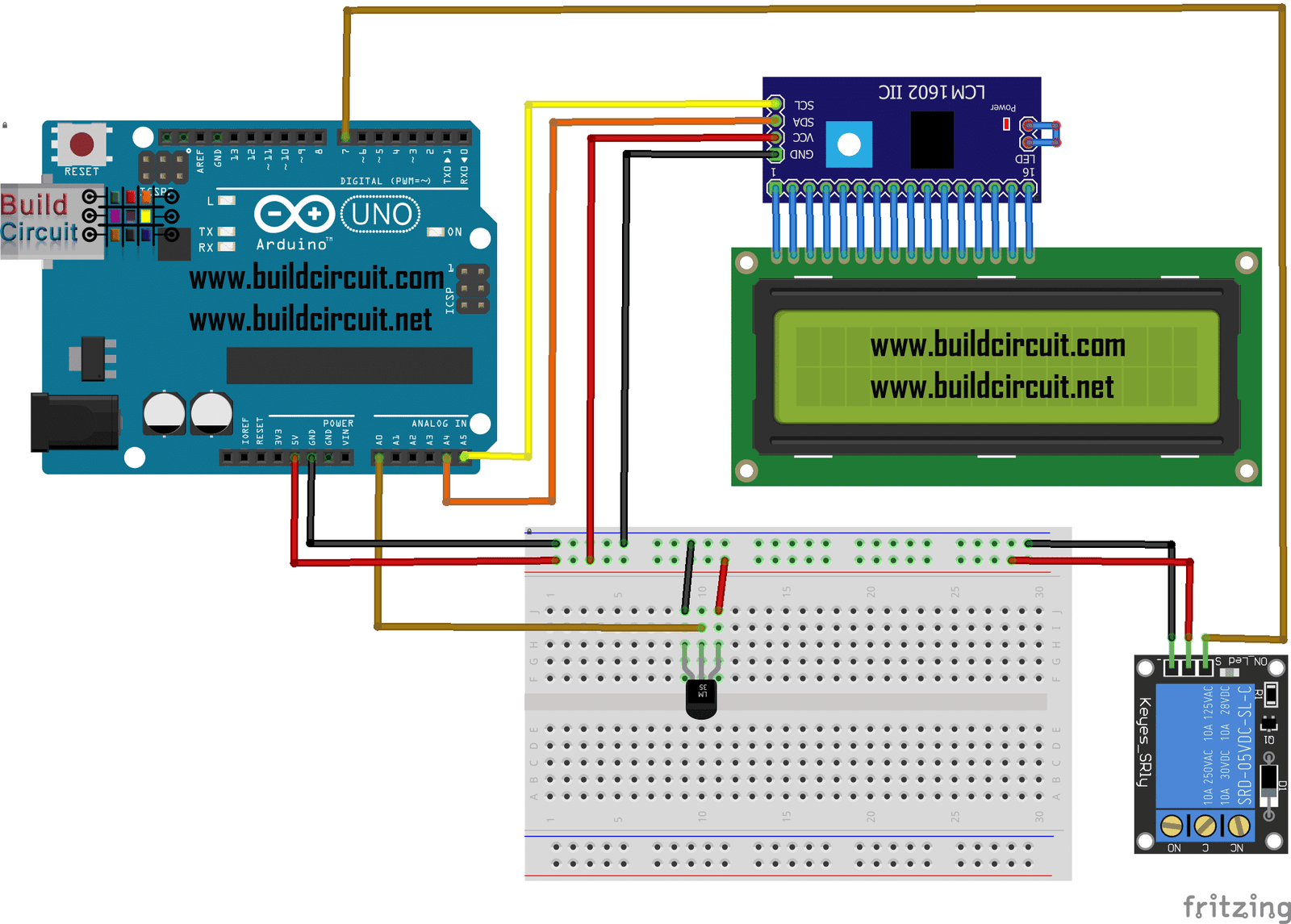
In this tutorial, we will build a thermostat to independently activate and deactivate any domestic device depending on the temperature. We will be able to display the temperature and the activation status of the device connected to the relay on the 16×2 LCD display. Moreover, on the sketch we can modify the temperature, detected by…
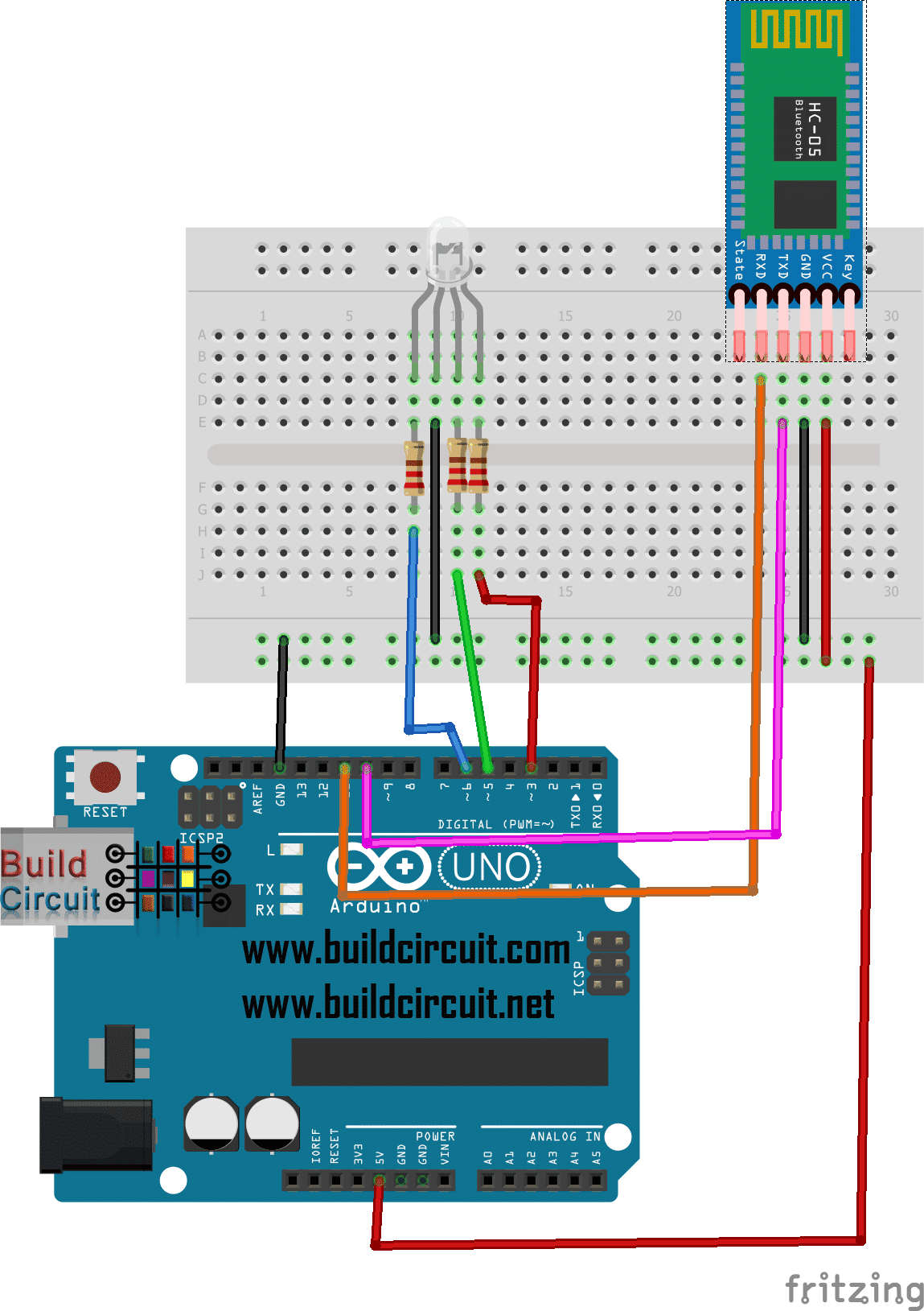
This is a project that we have done several times in the past. Serial communication between Arduino and Bluetooth is very easy. There are several apps available online that you can use to control Arduino using smart phone app and also send data from Arduino to your smart phone. In this particular experiment, we will…
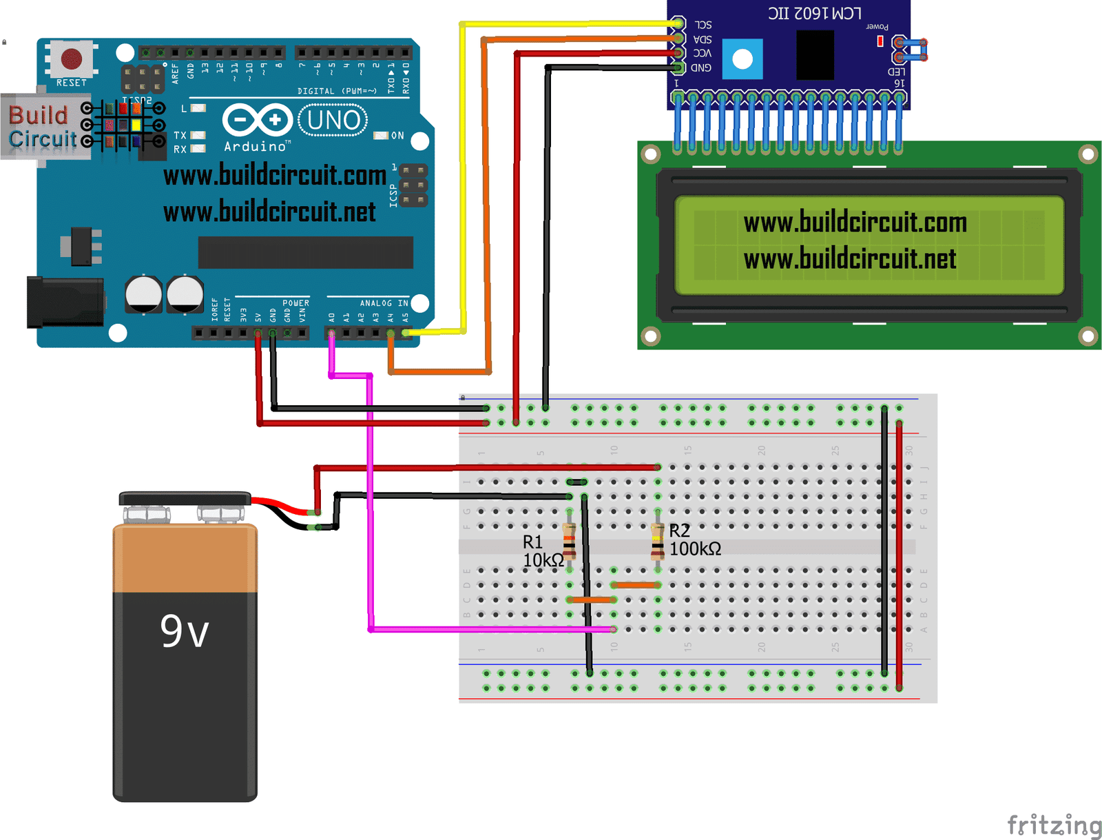
In this tutorial, we will build a circuit with Arduino Uno that can read voltages from 0 to 30V DC and display them on the 16×2 display, the ideal project to build our DIY voltmeter. Thanks to the analogue inputs, that can be used to measure voltages from 0 to 5V. For higher values we…
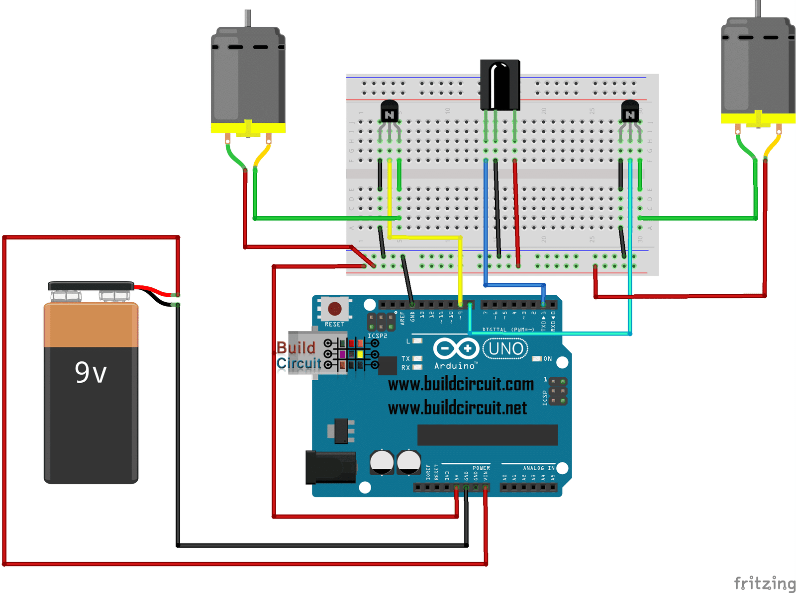
In this project, we will build an infrared remote-controlled car so that it can be controlled with any type of infrared remote control. By modifying the design of the robot avoids obstacles we will insert an infrared receiver TSOP4838 or VS1838B or a TSOP 1738 (they only change the pin configuration) instead of the ultrasonic sensor….
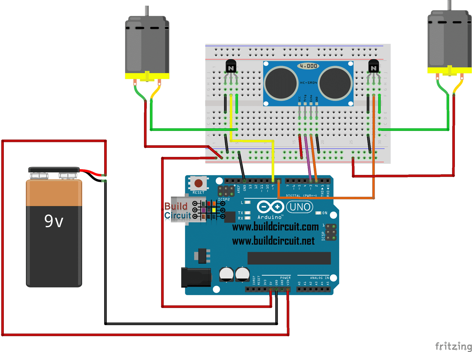
How many times have we wished to have a robot that goes around the house avoiding obstacles? Creating this project with Arduino Uno, an HC-SR04 module and two wheels will take us to be a child. The robot is able to avoid obstacles, thanks to the ultrasonic range finder sensor that senses obstacle coming on…
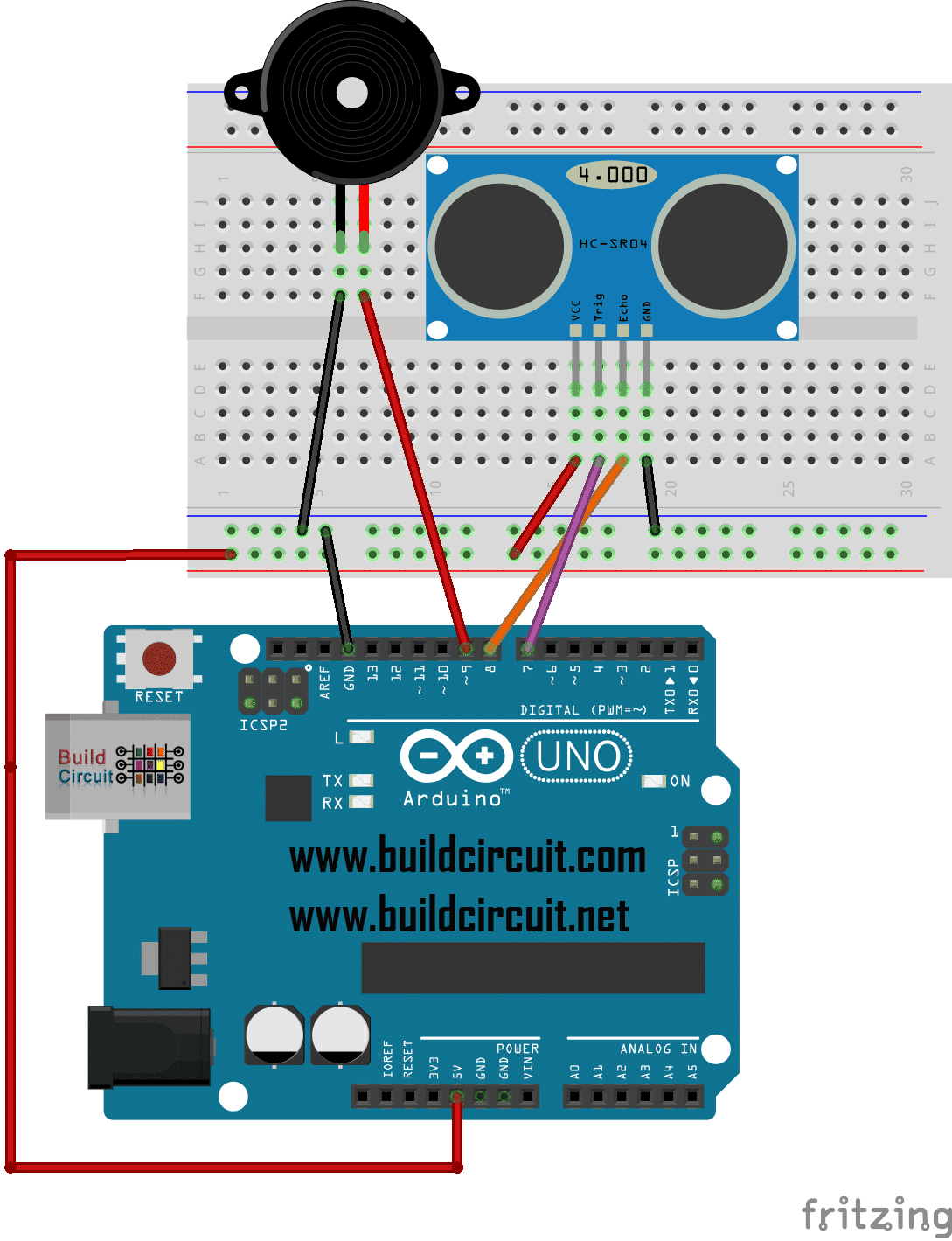
This is yet another ultrasonic range finder project using Arduino. We have done several similar projects in the past. It allows us to control a buzzer based on the distance detected by an HC-SR04 sensor, making it sound with a frequency proportional to the distance from an obstacle.

In this tutorial, we will learn how to move a servo through the values sent by a flex sensor. We can therefore take a step forward in creating robotic joints, such as moving arm hands and many other things.
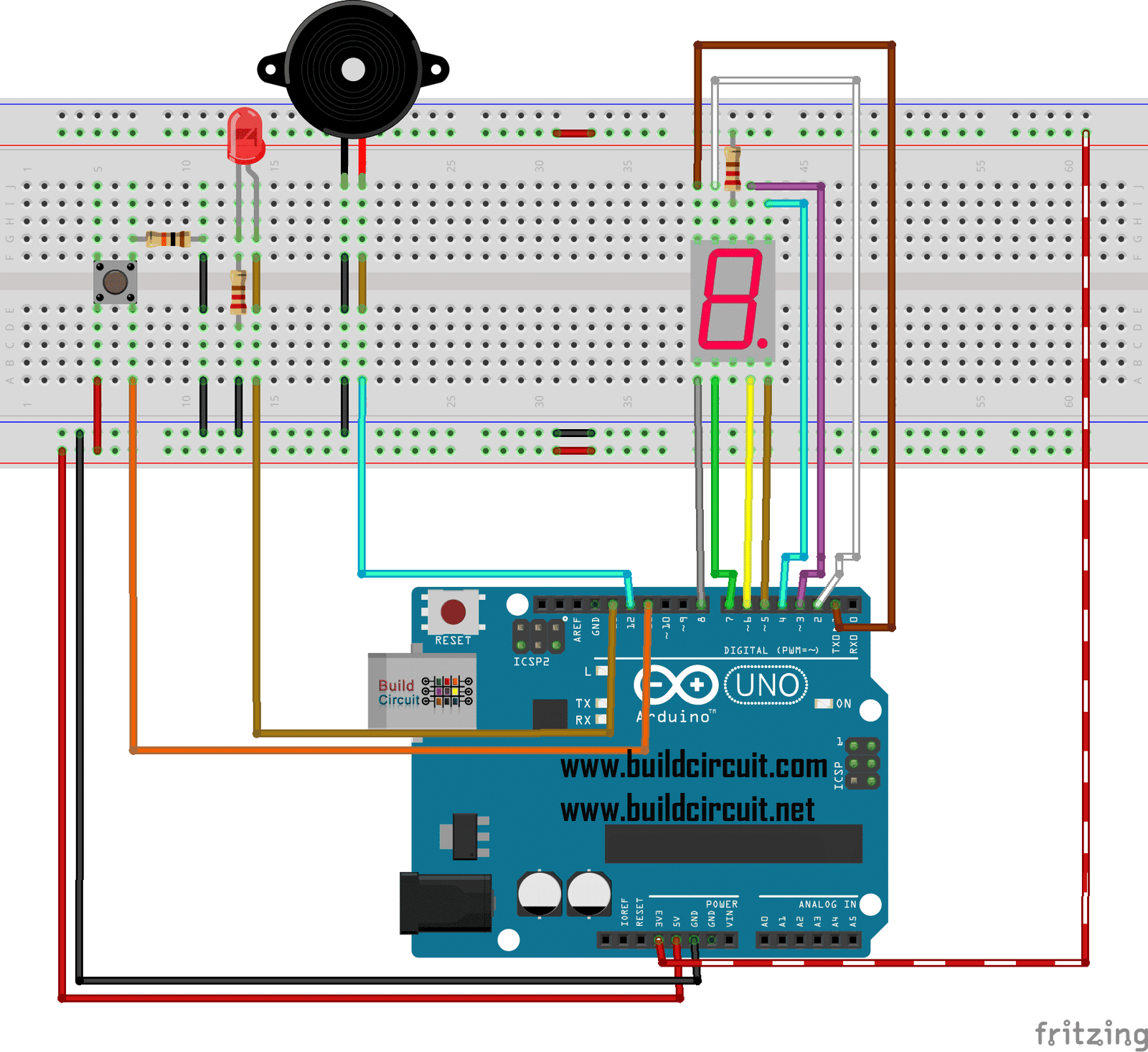
In this tutorial, we will learn to make a countdown seven segment display project that counts in a sequence from number 9 to 0. To start counting, you need to press the tactile switch. At the end of counting, it flashes the LED and rings the buzzer for a few seconds.
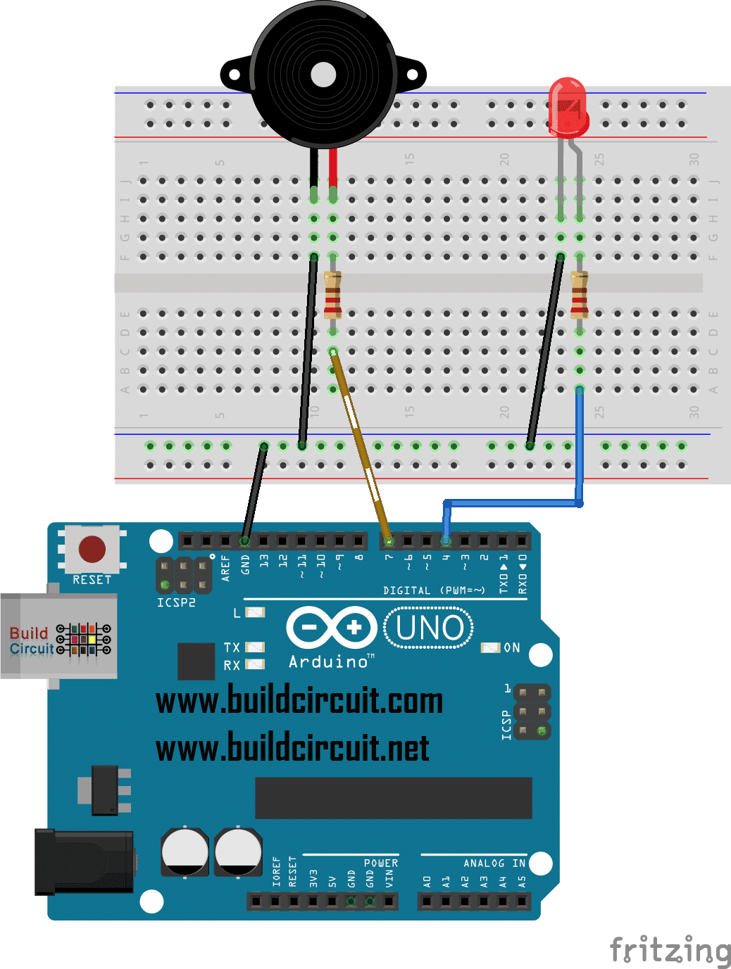
In this tutorial, we will learn to make a buzzer sound like an ambulance siren and at the same time we will flash an LED. We will learn to change the frequency of the sound to make a two-tone sound. If you want you can insert a potentiometer to increase or decrease the volume.
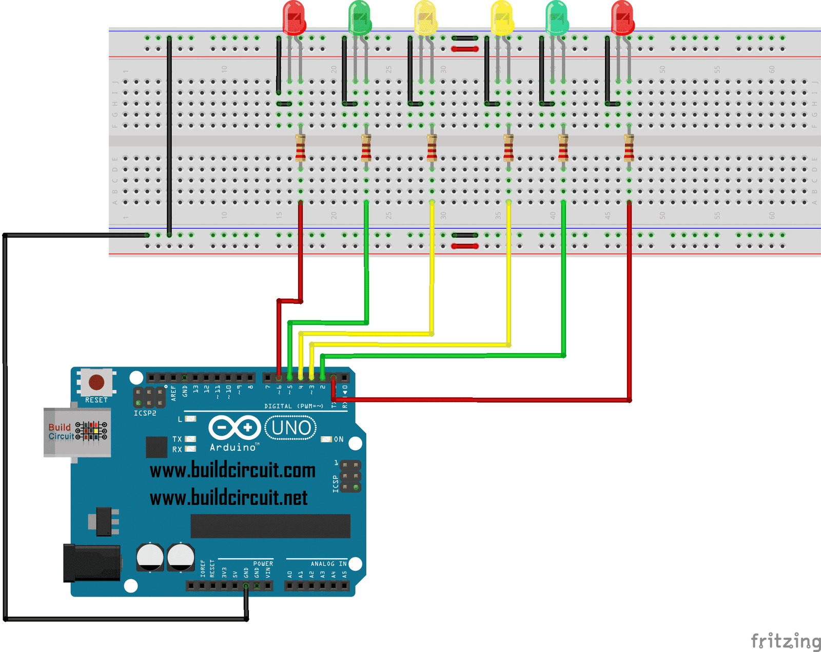
In this tutorial, we will turn on and off the LEDs sequentially, such as Christmas tree lights.
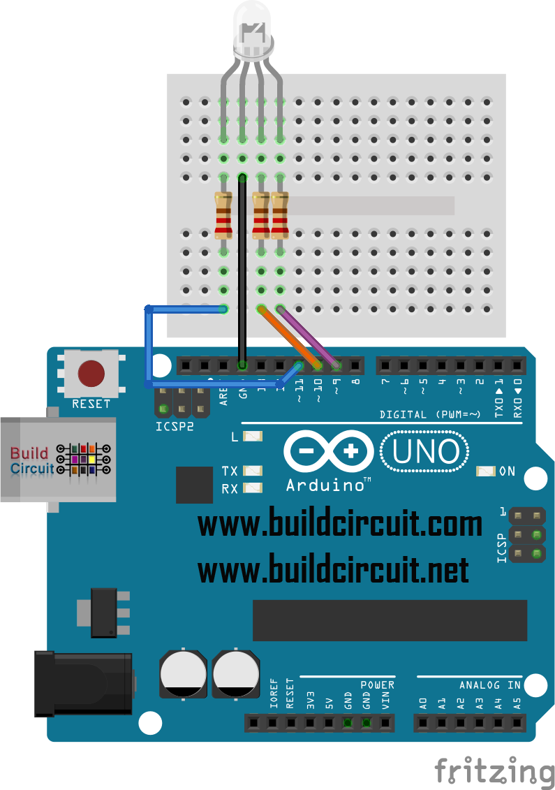
In this tutorial we will learn how to change the color of an RGB LED connected to Arduino, alternating for two seconds the following colors: red, green, blue, and then orange, yellow, indigo and purple. It is similar to the previous fade led effect experiment but it is not limited to only one LED but there…
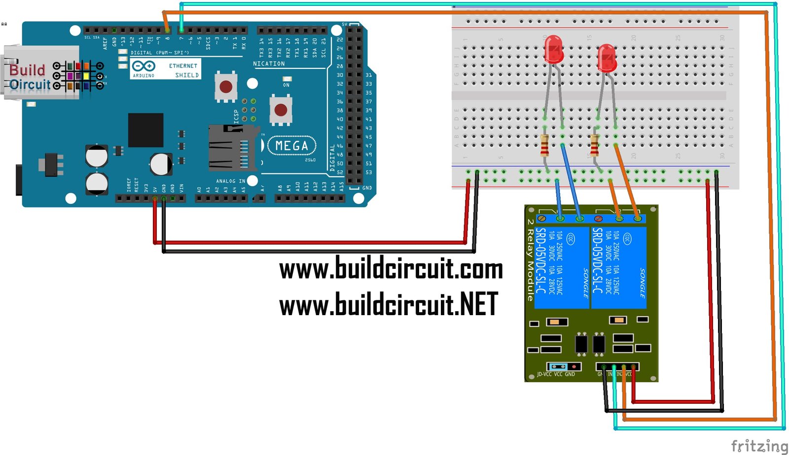
I found this project on Fritzing.org. This is just a simple project for testing a 2 channel relay using an Ethernet shield over an Arduino Mega. In place of LEDs, you can connect 220V AC lamps. If you have not used relay before, check out this article. The Arduino sketch has been compiled and there is…

In this tutorial, we will see how to use Arduino with a stepper motor and a joystick. To control the stepper motor we will use the driver control board that can drive up to about 750mA per port, so it is perfect to be used with this motor.
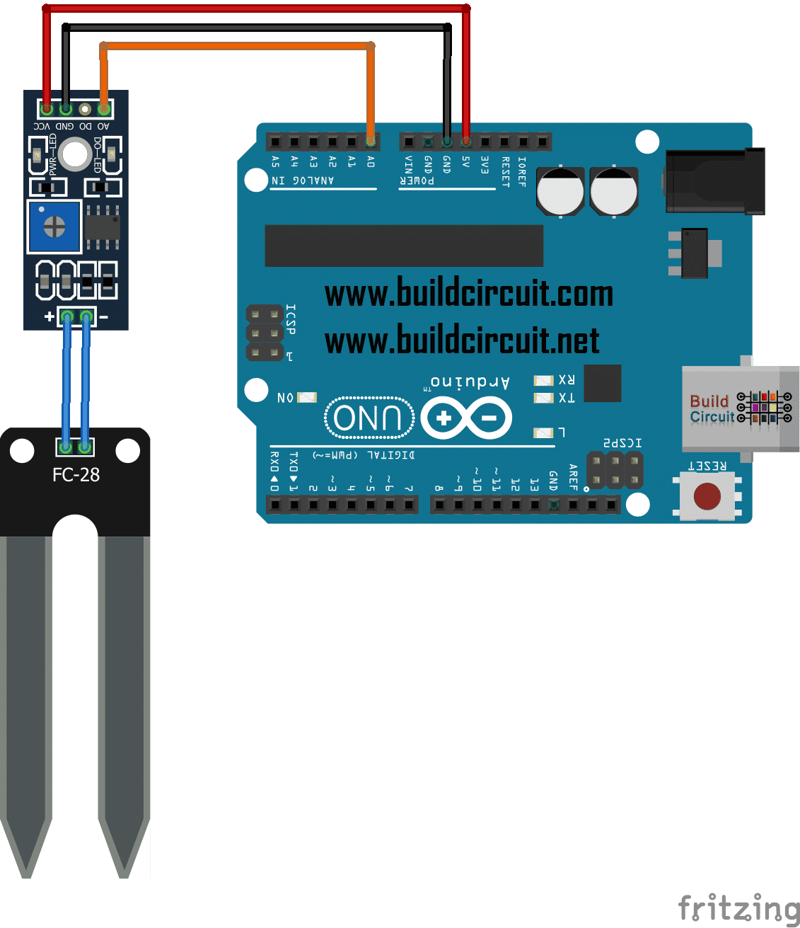
This small module helps you measure moisture of soil. It is a low cost sensor that you can purchase from Ebay. To modify the sensitivity of the soil moisture sensor, just rotate the potentiometer on the module.
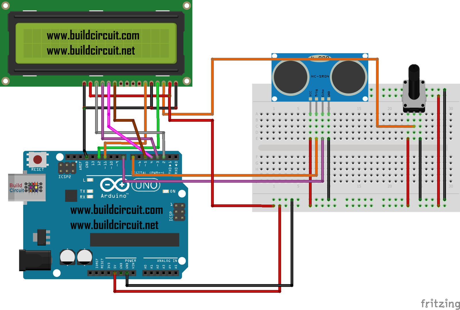
In this tutorial, we will build a digital ultrasonic distance meter. We will use a 16×2 LCD display to view the distance measured. We are using ultrasonic range finder HC-SR04 for this project. The HC-SR04 sensor measures the time taken by the sound waves transmitted after meeting an object that reflects them.

As stated on the title, in this tutorial, we will rotate a motor in both directions. To achieve this, we can use a switch or the serial monitor. We will need an integrated circuit chip (IC), called H-Bridge, we will use a L293NE or SN754410 chip for our experiment.

In this tutorial will use a rain sensor and we will turn on an LED if it is raining. In this case we used an LED but a buzzer can be also be used (see previous tutorials). This sketch will allow us to send a number on the serial port which is the value of…
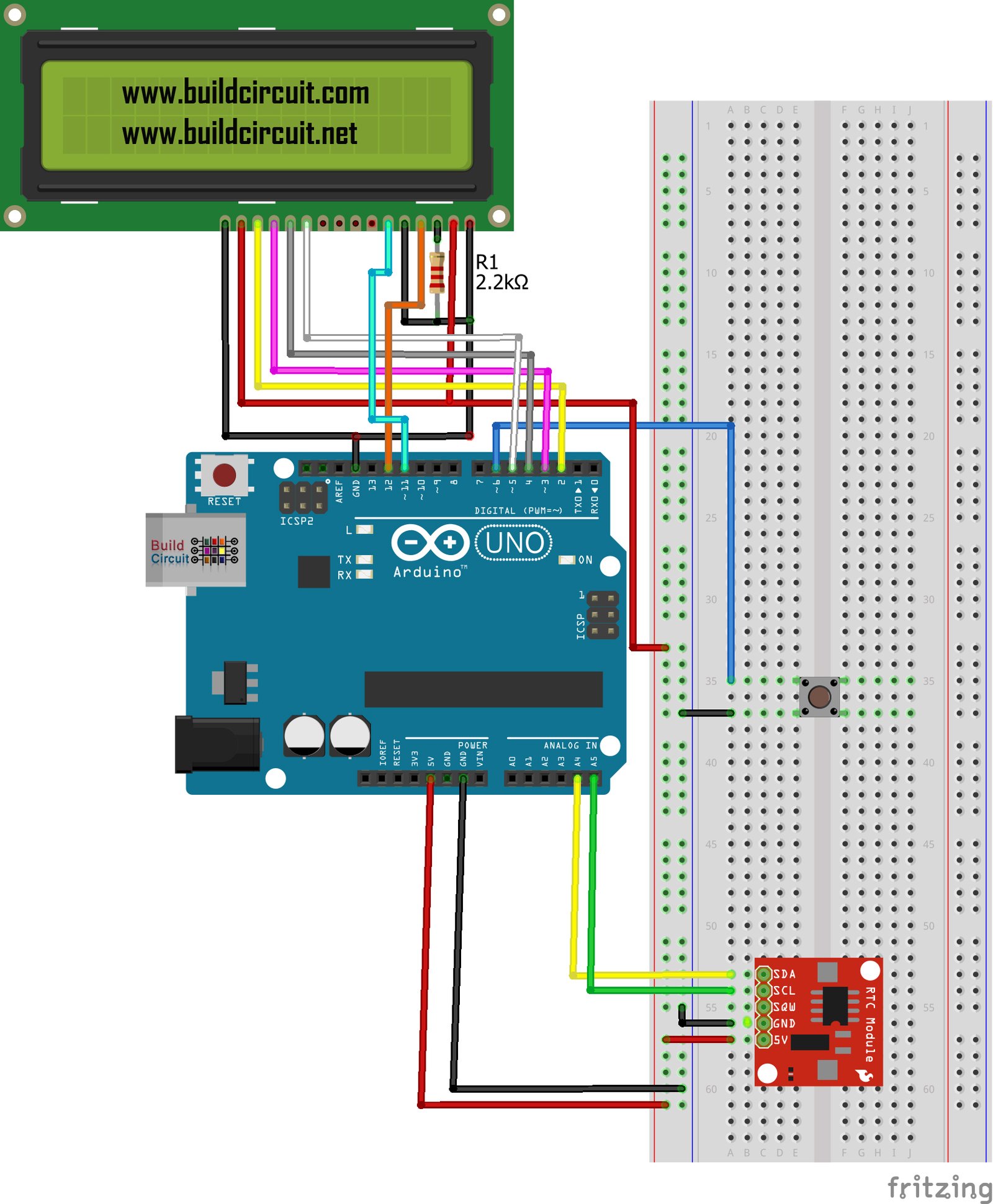
In this tutorial, we will learn to connect and use the RTC (Real Time Clock) module to display date and time on the 16×2 LCD display. DS1307 is called the Maxim-Dallas module for Arduino with which it allows us to have a precise system clock.
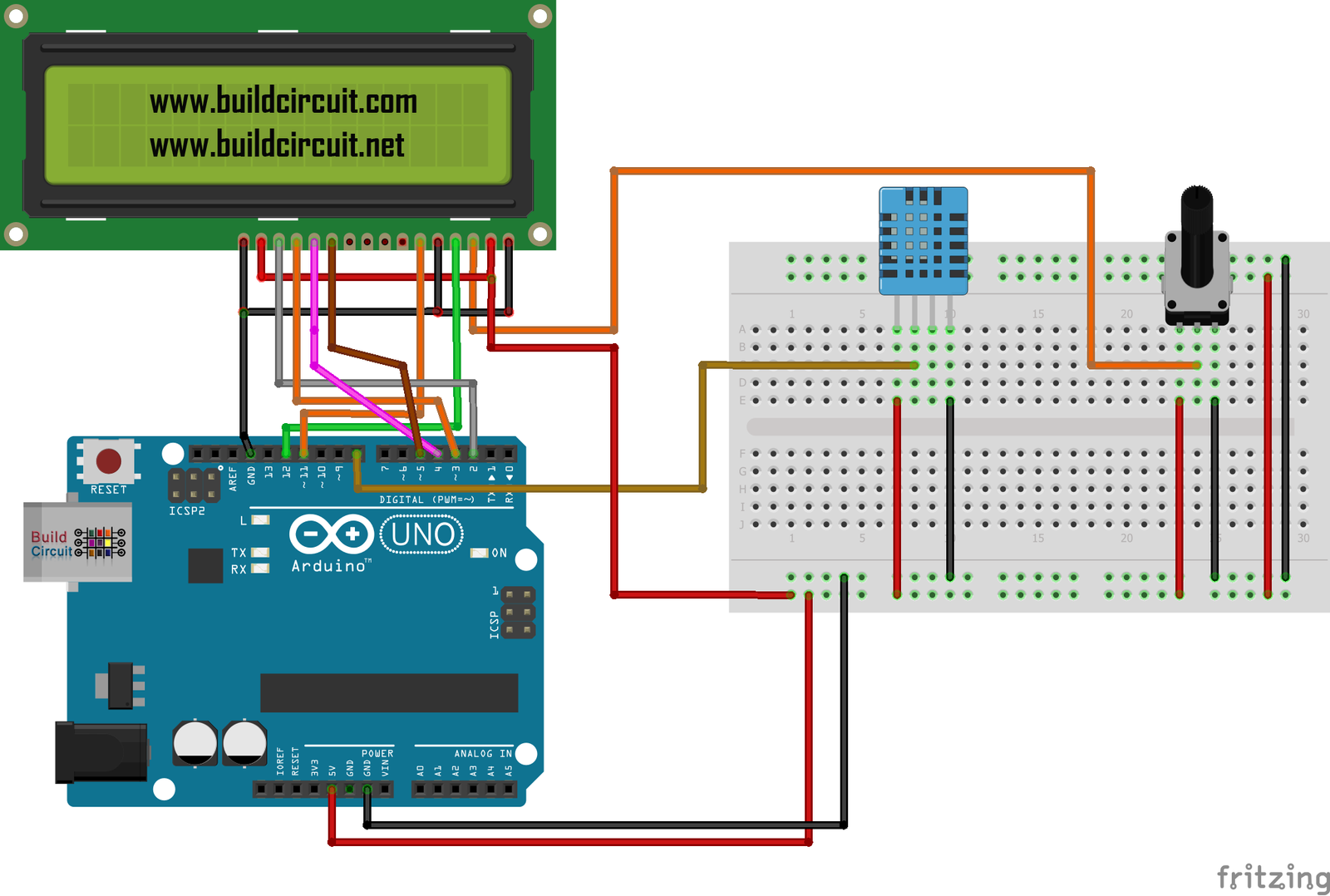
In this tutorial, will learn to use our Arduino board to display the temperature and humidity on the 16×2 LCD display using a DHT-11 sensor. For this project, you need to download the DHT11 library. You can download the library from this page. A long time ago, we had published a similar article. Please check…