


Infrared based music transmitter and receiver
NOTE: A similar kit is available at buildcircuit store. Please check the store.
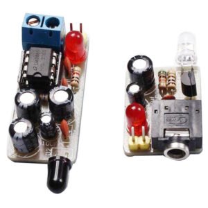
 An infrared based music transmitter and receiver is made up of three different modules. Test these three modules before you make this project.
You can make this project using phototransistor as well as photodiode.
Follow the following steps:
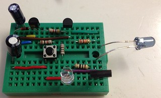
a. Make a melody generator using UM66 and replace the speaker with infrared LED.
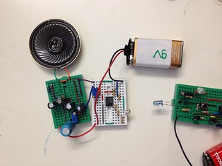
b. Remove LED from the 741 module and connect with Audio amplifier.

c. Orient infrared LED towards phototransistor/photodiode, you will hear the melody on the speaker.
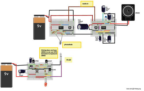
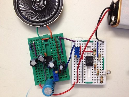
Schematic:
In this project, infrared LED is oriented towards phototransistor/photodiode. When melody generator is played, infrared LED transmits melody signals to photodiode. The signal is amplified by the 741 operational amplifier and fed to audio amplifier. You can control the volume of melody with 10K variable resistor connected to LM386.

(PLEASE IGNORE THE REPEATED NAMES OF COMPONENTS. TRY TO SEE THE PROJECT IN SEPARATE MODULES)
WATCH THE VIDEOS:
a. Circuit using phototransistor:
b. Circuit using photodiode:
You can buy a similar kit at buildcircuit store

🛠️ Dive into our collection of DIY Kits, 🔊 Audio Amplifiers, Digital Scoreboards, FM transmitters, and more!
🎶 Explore endless possibilities at our new store.


Hi sir
within how far this circuit can operate.and can i replace that speaker with relay.
It should operate from two meters. If you are trying to control a relay with remote control, I recommend you to go to this page: http://www.buildcircuit.com/object-counter/
And on this page, you can see, a circuit layout with mini breadboards, right below “a. Connect collector pin of infrared remote tester to positive terminal of electrolytic capacitor of RC module.”, make that circuit first, then I will tell you how to proceed ahead in another mail. First try that circuit. When you press a remote, it switch ON the red LED for some duration.
Write me back after you finish it. I will probably write you tomorrow again.
Sir thank u for ur circuit posted here, but I need to transmit audio from an amplifier using infrared , so how to modify ur circuit??
Plz reply soon….
I am doing it as my final year mini project.
So thank u in advance …..
i want to make this project. but i did not want to use modely genrator. i want to use mobile phone to transmit audio signal.please help me
i want to make this project.. but i did not want to use modely genrator. i want to use mobile phone with audio jack. so help me
sir i want to make this project but i have to use cell phone as a music transmitter instead of music modely.. please help
This is superb! Thank you for putting this down for us to learn from, I really appreciate your efforts. Please I’m a final year student from college, I need a circuit diagram on ” infrared Voice transmitter and receiver ” and the working principles. That is my project topic. Please sir I will be very grateful if can do this for me.
Thanks
Richard
hi sir,
Can I use ldr in place of phototransistor in Infrared Based Music Transmitter And Receiver Project.
Please help me.
because I have no photodiode.
sir, i want to transmit audio from my ipod.i have no need of um 66.how i will modify the circuit?
plz,plz help me.it’s urgent.
thanks
PLS
SIR, I AM USING INFRARED BASE MUSIC TRANSMITTER AND RECEIVER AS MY
PROJECT BUT HOW CAN I DO THE PROCEDURE FOR CIRCUIT CONSTRUCTION
(TRANSMITTER AND RECEIVER CIRCUIT), HOW CAN I DO THE CALCULATIONS AND
EXPLAIN WHY THE VARIOUS COMPONENT ARE USED. THAT IS, WHAT ARE THE
FUNCTIONS OF EACH OF THE ELEMENT.
Sir how can i transmit my voice with this device please reply.
Search on google
add a microphone and a resistor in it the circuit like ordinnary fm transistor
And also can i use a ldr instead of a photo-diode ?
NO
How do i do it without a melody transmitter
i want do this project. but i want use bluetooh not infrared. can u help me .