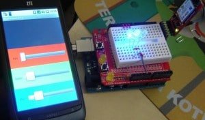
How to assemble Amarino Evaluation Shield

SEE ALL THE PHOTOS ON FLICKR This post shows you how to build the Amarino evaluation shield.

When you buy the shield package, you will get the following components.

Fully assembled kit is now available on buildcircuit.net.

The PCB:

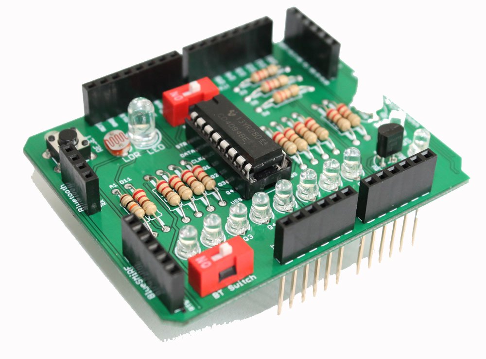
PCB clearly shows the pin and component names, so, it should help you to get idea of connections of components to Arduino. If you just follow the names of components on the PCB, it is possible to assemble the whole kit without reading the rest of this post. However, I have shown all the important steps.

Step 1: Always start with the smallest component. So, start with resistors. Fix resistors 220R.

Step 2: Then fix 10k resistor.

Step 3: Then, fix LDR and 5mm white LED.

Step 4: Fix tactile switch

Step 5: Fix LM35.

Step 6: Fix RGB LED. It is common cathode type RGB LED.

Step 7: Solder all the female headers.

Step 8: Solder 10k variable resistor and 1 position DIP switch,

Step 9: Fix 16×2 LCD. While soldering the header the 16×2 LCD, the longer part of header should be on the upper side of PCB. Please see the picture below:

When you purchase the kit, you may get a slightly different LCD that needs to be fixed in the following way:

Step 10: Solder 4 pcs of male headers on the PCB to stack the shield over the Arduino.

Your shield is ready 🙂 .

Stacking adapter: You can stack either BlueSMiRF mate silver or general Bluetooth adapter over the shield. See the following pictures how they are stacked.

First Experiment: Test if the LCD is working- source code   Download source code  Watch the video to know how to change the contrast level of LCD. Move the 10k variable resistor screw in the clockwise direction to increase the contrast level. After you confirm that the LCD is working, modify the source to test RGB LED, LDR, LM35DZ and 5mm LED. Check the schematic and circuit layout.


Check out all the experiments with Amarino Evaluation shield


try this also

Fully assembled kit is now available on buildcircuit.net. Watch all the videos (Playlist):

try this also

Amarino Lamp- Assembly tutorial

Recommended app

If you come to this page randomly from a search engine, please check this page first, you will eventually come back to this page.

About Amarino Lamp

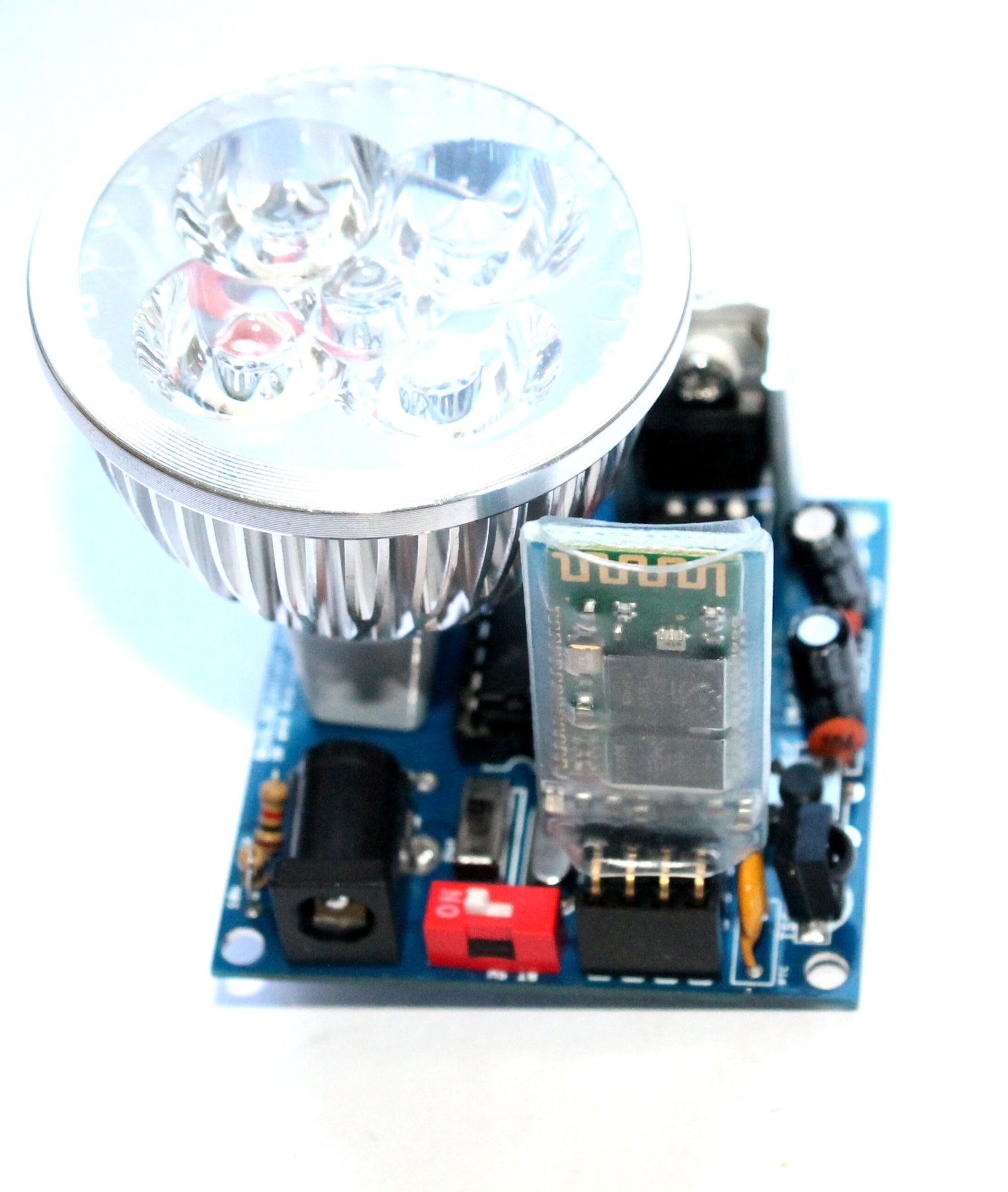
This post shows you how to assemble the Amarino lamp. The kit package includes the following components. Click on the links of the components the components below to see how the components have been assembled on the circuit board.

You will need basic soldering knowledge to assemble the kit. The assembly process is very straight forward, you can easily guess which components to solder where on the PCB. The silkscreen labels are very clear and directs you to assemble the board properly.

  1. 1 x Bare PCB with silkscreen indicators. (click on the links to see the assembly images)
  2. 2 x 22pF ceramic capacitors  (step 1)
  3. 1 x 0.1uF ceramic capacitor   (step 2)
  4. 1 x 16Mhz crystal oscillator   (step 3)
  5. 1 x 1N4001 diode                  (step 4)
  6. 1 x 3mm LED                         (step 5)
  7. 1 each x 10K and 1K resistors (step 6) 
  8. 1 x TSOP4838 infrared sensor (step 7)
  9. 1 x tactile reset switch             (step 7)
  10. 1 x 500mA PTC resettable fuse (step 8)
  11. 1 x 1P DIP switch  and 1 x SPDT switch (step 9)
  12. 1 x 4 pin female header            (step 10)
  13. 1 x 28 pin DIL socket                (step 11)
  14. 1 x 16 pin DIL socket                (step 12)
  15. 1 x 6 pin male header for FTDI basic breakout board (step 13)
  16. 2 x 10uF electrolytic capacitor (step 14)
  17. 1 x DC barrel                             (step 15)
  18. 1 x LM7805 with heat sink       (step 16)
  19. 1 x LED lamp                             (step 17)
  20. 1 x Bluetooth module               (step 18) (you need to stack this Bluetooth module while using the kit)
  21. 1 x ULN2003 and 1 x Atmega328P with Arduino Bootloader (Insert these chips in the respective DIL sockets)

Documents: 

Where can you buy ?

buildcircuit   etsy

Display SMS on LCD using Amarino evaluation shield

Tutorial for Amarino Beginners- Display your SMS on 16×2 LCD.

This tutorial shows you how to display SMS on 16×2 LCD. This tutorial is based on Amarino. It utilizes Receive SMS plugin of Amarino. This plugin sends the first 30 characters of a received SMS to Arduino. The message is sent as a string. The length of the string can be between 0 and 30.

(more…)

Amarino Evaluation Shield

After the success of BuildCircuit’s first Amarino Shield for Android-Arduino experiments, we are here with Amarino Evaluation Shield. I am grateful to all the customers and readers who purchased our first kit and gave us their wonderful comments.

About Amarino Evaluation Shield:

Amarino Evaluation Shield is for Amarino toolkit and most of the available Android VT-100 serial terminal emulators. With Amarino evaluation shield, you can test all the plugins of Amarino, practically speaking, you can do all the Amarino related experiments. Besides, you can try simple Android-Arduino experiments using Android VT-100 serial terminal emulators.

(more…)

Experiments with Amarino Evaluation Shield

Before you read this post, please read the following  posts:

a. Introduction to Amarino evaluation shield.

b. Amarino evaluation shield assembly tutorial.

You can do several experiments with Amarino evaluation shield, for example, control RGB LED, visualize sensor graph on Android phone, display SMS on LCD, etc.  Before we start the experiments, let’s check the circuit layout of the shield. The layout has been made using Fritzing (www.fritzing.org).

(more…)

Assembly instructions for Amarino 3.0 DIY shield

Step 13- Solder stackable header

This post gives you the idea for assembling the Amarino shield. To get full details about this shield,  CLICK HERE.  When you buy the kit package, you will get the following PCB. The PCB clearly shows the pin and component names, so, it should help you to get idea of connections of components to Arduino.  For example, LDR is connected to A1 and RGB LED is connected is to D3, D5 and D6 and you can see those pins labeled on the PCB. (more…)

Amarino DIY shield for Android-Arduino-Bluetooth experiments

We are now selling Amarino Nano 1.0 kit for Amarino experiments. It is fully assembled kit and includes Arduino Nano and Bluetooth module. You can easily test RGB LED and sensor graph features of Amarino toolkit app.

 Please check this page for more information. 

Amarino Nano-1-1


About Amarino Shield

Amarino shield in use (2)

Amarino shield can be used for doing several experiments with Amarino and Android serial emulators. For example, you can operate a multicolor lamp, sensor graph, light sensor, etc.

The shield is just a modification of previous shield designed and published by Sagar Sapkota (Buildcircuit.com). Amarino shield 3.0 has added one more header space for BlueSMiRF supporting altogether 3 different Bluetooth adapters.

(more…)

Amarino shield 3.0 experiments- Android and Arduino

On this post, you will see how Amarino shield can be used for Android- Arduino experiments. It shows some basic experiments with android serial emulator and Amarino toolkit. You can get the original Amarino source codes and installable files also. Just install the application on your Android phone and experiment with the kit.

This page basically gives examples for using Amarino 3.0, but you can also use the same source codes for Amarino shields 1.0 and 2.0.

(more…)

Amarino based Sensor Graph with Custom Bluetooth ID and LED controller

In this project, you can control an LED and see sensor graph simultaneously. For your convenience, I have used a simple light sensor circuit. The resistance of the photo resistor varies with the amount of light falling on it. The amount of light is varied with LED controller and the sensor data variation can be seen on the Sensor Graph.

Amarino project- Arduino and Android based light sensor

With this project/application, you can make a light sensor dependent lamp. You can make a light sensor or dark sensor with this application.

The light sensor of your Android smart phone senses ambient light present in your room and sends commands to Arduino board. Your Arduino program determines the behaviour of the LED, whether it should glow bright or dim. You can also see the light sensor data on the smart phone interface. (more…)

3 useful applications for serial data transfer between Android and Arduino

In this article, you will know about three easy, useful and absolutely FREE Android applications that facilitate serial communication between Arduino and Android via Bluetooth medium. Before moving on to applications, you can check this article to know about the fundamentals of Android-Arduino communication using Bluetooth.

Now, let’s start with the applications first, then we can move on to some simple experiments. (more…)

Multi color Lamp using Amarino, Android and Arduino

This tutorial is for novices who have never made any Android application or worked with Amarino. If you have never done any experiment with Android and Arduino, please start with this experiment.

You don’t need to have previous knowledge of Android for doing this experiment. Simply download any Android serial emulator and upload the Arduino code and send/receive between Arduino and Android. For that experiment, you can use any kind of Bluetooth adapter, for example, BlueSMiRF or general Bluetooth adapter. If you are not confident, start with a cheap Bluetooth moduleBUY HERE. (more…)

Search for products

Back to Top
Product has been added to your cart