DIY KIT 17- DIY ZIF Arduino programmer

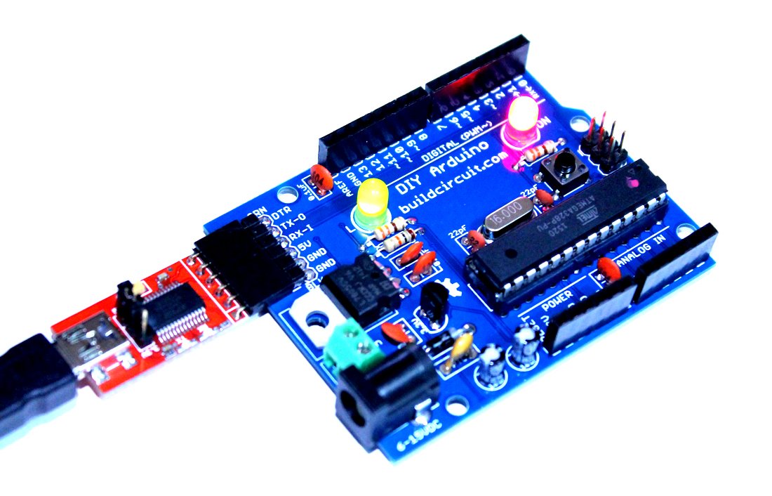
It is just another ‘build your own Arduino’ project. BuildCircuit has worked on similar projects before. The most popular project is a DIY Arduino kit. The DIY Arduino looks similar to the real Arduino boards and uses an FTDI basic programmer to program the chips.

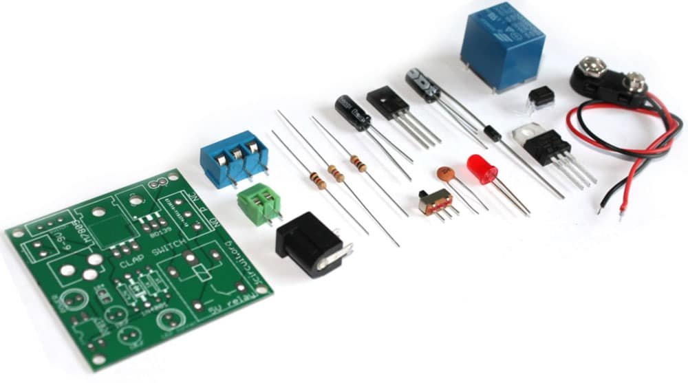
The kit that we are going to work on this article is also a DIY Arduino. It comes with a zero insertion force (ZIF) IC socket. You can simply insert an Arduino chip and program it. The board has a header to connect an FTDI basic module that can be used to program the Arduino chip.

(more…)

Assembly Tutorial of Amarino Nano 1.0

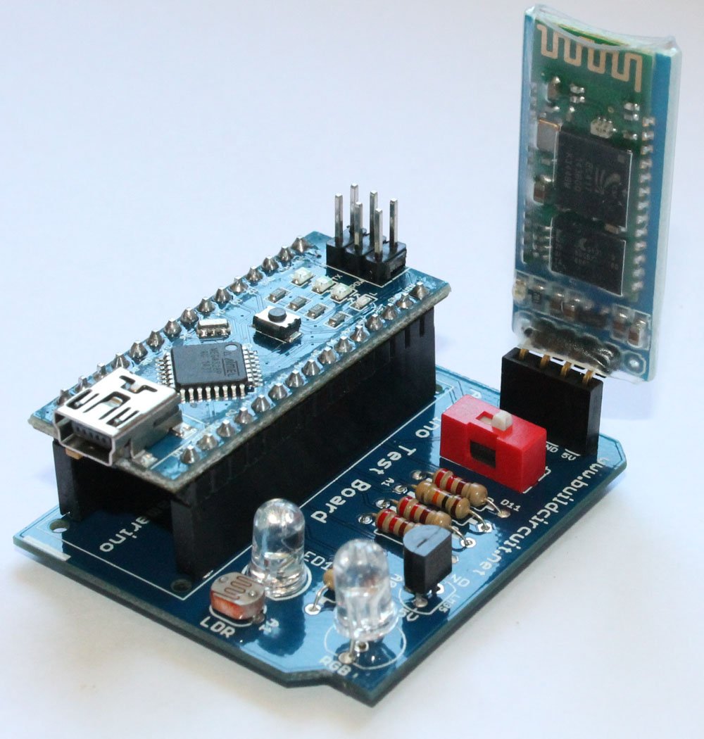
Amarino Nano 1.0

Please visit this page first to know about Amarino Nano.

Assembly process of this kit is very easy. If you have basic soldering knowledge, you can assemble the board within half an hour.

You can directly visit BuildCircuit’s Flickr page and see all the assembly steps.

If you look at the PCB, you will see that the silkscreen labels are enough to guide you to solder the components properly.

PCB

Before you start, make sure that you have all the required components.

Here’s the list of components:

  • 1 x Arduino Nano
  • 1 x Bluetooth adapter
  • 1 x Amarino Nano PCB
  • 2 x 15 pin female headers
  • 1 x 4 pin female header
  • 1 x Red Color 1P DIP switch
  • 1 x LM35DZ temperature sensor
  • 1 x 5mm LED
  • 1 x RGB LED- common cathode
  • 1 x photo resistor
  • 4 x 220 Ohm resistor
  • 1 x 10K Ohm resistor

Now, follow these steps:

1. Always start with the small components. So, solder all the resistors first. Solder 220 Ohm resistors.

Step 2- Solder resistor that connects to D11

2. Solder 10K Ohm resistor and the photo resistor

Step 3- Solder 10K Ohm resistor

3. Solder LM35DZ temperature sensor.

Step 5- Solder LM35

4. Solder 1P DIP switch, the one in RED color. This switch has to be turned off while uploading the Arduino sketch.

Step 6- Solder 1P DIP switch

5. Solder 5mm white LED

Step 7- Solder 5mm LED

6. Solder common cathode RGB LED

Step 8- Solder RGB LED Step 8.2- RGB LED top view

7. Solder 4 pin female header for Bluetooth moduleStep 9- Solder 4pin female header

8. Solder 2pcs 15 pin female header to stack the Arduino NanoStep 10- Solder 15 pin female headers

9. Stack the Bluetooth module and the Arduino Nano on the correct female headers. Your Amarino Nano board is ready to use. Visit this page for experiments.

Step 11- Fix Arduino Nano and Bluetooth Module

10. Connect a mini USB cable to operate the kit.

Connect USB cable and use the kit

See the following links:

1. About Amarino Nano 1.0

2. Experiments with Amarino Nano 1.0– You will get all the Apps and Arduino sketches on this page.

3. All the images on Flickr


Where can you buy this kit ?

The kit is available at BuildCircuit Store (www.buildcircuit.com.au- Free Shipping in Australia)

Amarino Nano-1-1Buy now button

Cosmarino Assembly Tutorial

If you have come to this page from a search engine, please check this page first, you will eventually come to this page again.

About Cosmarino

The assembly process of the Cosmarino kit is very straight forward. You just need to follow the silkscreen labels to get the idea of assembly. A basic knowledge in soldering is enough for assembling the kit.

To be quick, you can see all the assembly images on Flickr. 

Step 1: Solder all the 220 ohm resistors

Step 1- Solder 220 Ohm resistors

Step 2: Solder 330 Ohm and 10K ohm resistors

Step 2- SOlder 330 Ohm and 10K Ohm resistors

Step 3: Solder 1N4001 diode.

Step 3- Solder 1N4001 Diode

Step 4: Solder LDR/ photoresistor.
Step 4- Solder LDR

Step 5: Solder BD139 NPN transistor
Step 5- Solder BD139 NPN transistor

Step 6: Solder LM35DZ temperature sensor
Step 6- Solder LM35 temperature sensor
Step 6.1- LM35 temperature sensor

Step 7: Solder TSOP4838 infrared sensor
Step 7- Solder TSOP4838 infrared sensor

Step 8: Solder 1P DIP switch
Step 8- Solder 1P DIP switch

Step 9: Solder 5mm white LED
Step 9- Solder 5mm White LED

Step 10: Solder RGB LED
Step 10- Solder common cathode RGB LED
Step 10.1- RGB Common cathode LED

Step 11: Solder 2pcs 15 pin female header
Step 11- Solder 4 pin and 15 pin female headers

Step 12: Solder 3 pin screw terminal
Step 12- Solder 3 pin screw terminal
Step 12.1- 3 pin screw terminal

Step 13: Solder 5V relay
Step 13- Solder 5V relay

Step 14: Stack Bluetooth module and Arduino Nano
Step 14- Stack Bluetooth module and Arduino Nano

The kit is ready to use
Step 15- Use Mini USB cable to program Arduino Nano - Copy


Cosmarino Experiments


Related documents:

Where can you buy ?

buildcircuit   ebay   etsy

Amarino Lamp- Assembly tutorial

Recommended app

If you come to this page randomly from a search engine, please check this page first, you will eventually come back to this page.

About Amarino Lamp

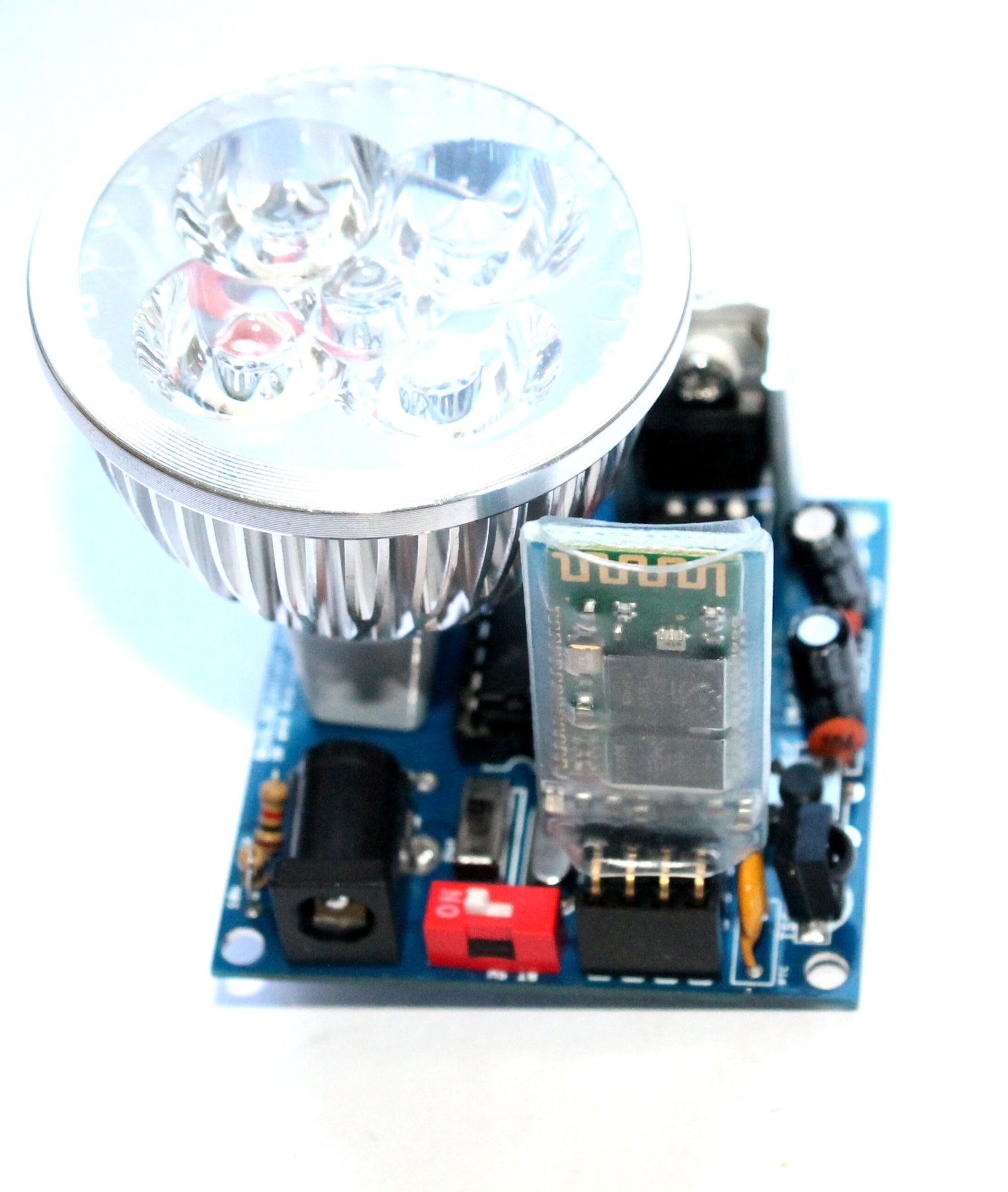
This post shows you how to assemble the Amarino lamp. The kit package includes the following components. Click on the links of the components the components below to see how the components have been assembled on the circuit board.

You will need basic soldering knowledge to assemble the kit. The assembly process is very straight forward, you can easily guess which components to solder where on the PCB. The silkscreen labels are very clear and directs you to assemble the board properly.

  1. 1 x Bare PCB with silkscreen indicators. (click on the links to see the assembly images)
  2. 2 x 22pF ceramic capacitors  (step 1)
  3. 1 x 0.1uF ceramic capacitor   (step 2)
  4. 1 x 16Mhz crystal oscillator   (step 3)
  5. 1 x 1N4001 diode                  (step 4)
  6. 1 x 3mm LED                         (step 5)
  7. 1 each x 10K and 1K resistors (step 6) 
  8. 1 x TSOP4838 infrared sensor (step 7)
  9. 1 x tactile reset switch             (step 7)
  10. 1 x 500mA PTC resettable fuse (step 8)
  11. 1 x 1P DIP switch  and 1 x SPDT switch (step 9)
  12. 1 x 4 pin female header            (step 10)
  13. 1 x 28 pin DIL socket                (step 11)
  14. 1 x 16 pin DIL socket                (step 12)
  15. 1 x 6 pin male header for FTDI basic breakout board (step 13)
  16. 2 x 10uF electrolytic capacitor (step 14)
  17. 1 x DC barrel                             (step 15)
  18. 1 x LM7805 with heat sink       (step 16)
  19. 1 x LED lamp                             (step 17)
  20. 1 x Bluetooth module               (step 18) (you need to stack this Bluetooth module while using the kit)
  21. 1 x ULN2003 and 1 x Atmega328P with Arduino Bootloader (Insert these chips in the respective DIL sockets)

Documents: 

Where can you buy ?

buildcircuit   etsy

Assembly Tutorial- 3 Digits – Digital object counter DIY kit

We are now selling CD4026 and CD4029 up and down counter modules.

Step 15- Connect a 9V battery and your kit is readyThis page shows you how to assemble three digit digital object counter. If you are looking for 2 digit digital object counter please see this page.

If you are interested in knowing about this 3 digit counter, please check this page. 

The counter module kit package comes with all the components required to build your kit. Before you proceed, please check if you have all the required components:

  • 1 x TO-92 5V Voltage Regulator(78L05)
  • 3 x CD4026 Decade counter
  • 3 x 16-pin IC socket.
  • 3 x common cathode seven segment display-(Can be in red, yellow and blue colors)
  • 1 x TSOP4838 Infrared sensor
  • 1 x 100uF Capacitor- (Voltage rating can be between 16V to 50V- causes no problem in operation)
  • 2 x 0.1uF 50V ceramic Capacitor
  • 2 x 3mm LED- (can be any color)
  • 1 x BC547
  • 1 x BC557
  • 1 x SPDT Slide Switch
  • 1 x Tactile reset switch
  • 1 x Screw terminal- (can be in blue/green colors)
  • 4 x 1K Ohm Resistor 1/4W
  • 1 x 330R Resistor 1/4W
  • 1 x 10K Ohm Resistor 1/4W
  • 1 x Bare PCB with Silkscreen Indicators
  • 1 x 9V battery connector

Please follow the following steps:

Step 1: Solder 1K Ohm resistors. The color code of 1K ohm resistor is Brown-Black-Red

Click on the image to see the color code more clearly.

Step 1- Solder all the 1K Ohm resistors

Step 2: Solder 10K Ohm resistor and 330 Ohm resistors. The color code for 10K Ohm resistor is Brown- Black- Orange and color code of 330 Ohm resistor is Orange-Orange-Brown.

Step 2- Solder 330 Ohm and 10K ohm resistors

Step 3: Solder 2pcs 0.1uF (code- 104) capacitors.

Step 3- Solder 2pcs 0.1uF(104) code capacitor

Step 4: Solder 2pcs 3mm LED. If you do not know which pin is Anode and which is cathode, please see this. The longer pin is Anode and the shorter pin is Cathode.

Step 4- Solder 2pcs 3mm LED

Step 5: Solder tactile switch. The switch is for resetting the counter. You can see how it work on the video below.

Step 5- Solder tactile switch

Step 6: Solder BC557 PNP transistor.

Step 6- Solder BC547 transistor

Step 7: Solder BC547 NPN transistor

Step 7- Solder BC557 transistor

 Step 8: Solder 5V voltage regulator. The 5V regulator chip is marked as 78L05. It is in TO-92 package.

TO-92 5V regulator

Step 8- Solder 5V regulator

Step 9: Solder TSOP4838 infrared sensor.

Step 9- Solder TSOP4838 infrared sensor

Step 10: Solder SPDT switch. It is used for switching ON/OFF the counter module.

Step 10- Solder SPDT switch

Step 11: Solder 2 pin screw terminal. It is used for connecting a 9V battery to the counter module.

Step 11- Solder 2pin screw terminal

Step 12: Solder 3pcs of 16 pin DIL sockets. These are used for stacking CD4026 chips. Step 12- solder 3pcs 16 pin DIL sockets

Step 13: Solder three seven segment displays and 100uF Capacitor. Please notice the + and – terminal of the capacitor. Solder it correctly.

Step 13- Solder 3pcs common cathode seven segment display

Step 14: Put CD4026 chips over the DIL sockets.

Step 14- Solder 100uF capacitor and insert CD4026 chips

Step 15: Use a 9V battery to operate the kit. Your kit is now ready to use.

Step 15- Connect a 9V battery and your kit is ready
Other related tutorials:


BC-3014A

3 Digit Digital Objects Counter With Laser Module

US $14.95US $19.95
This is 3 digits digital object counter kit

Check out all the counters

COU-18

1.8" Photoresistor And Laser Operated Medium Digital Objects Counter

US $24.95
This is an upgraded version of the previous
SCO-23

2.3" Common Anode Seven Segment Display Driver

US $19.95
COU-902

2.3" common cathode seven segment display driver

US $14.95US $19.95
This is a CD4026 based up counter driver

CD4026- 1 Digit Up Counter Module

US $4.95
  • It works as an UP counter. You can
Sold out
COU-23

Photoresistor And Laser Operated Large Digital Objects Counter With 2.3" Displays

US $29.95
A laser light module illuminates the photoresistor continuously

Assembly tutorial- Relay module DIY kit for popular clap switch

connecting a lamp

In this article, we have described how you can assemble your relay module for the popular clap-switch. If you have come to this page from a search engine, we recommend you to visit the following pages:

Related articles:

1. About Relay module for the popular clap_switch (Get description of this kit)

2. How to connect clap-switch to the relay module

3. How to use the relay-module and the clap-switch to operate electrical appliances

You can see the following steps to make your relay module for the popular clap-switch.

PCB

Step 1: Solder 2pcs of 1K resistor and 4.7K resistor

Step 1- Solder 4.7K and 1K resistors

Step 2: Solder 1N4001 diode

Step 2- Solder 1N4001 diode

Step 3: Solder LM7805 voltage regulator and BD139 transistor

Step 3- Solder LM7805 and BD139

Step 4: Solder 0.1uF capacitor

Step 4- Solder 0.1uF capacitor

Step 5: Solder PC817 optocoupler

Step 5- Solder PC817 optocoupler

Step 6: Solder SPDT switch and 2 pin screw terminal

Step 6- solder SPDT switch and 2 pin screw terminal

Step 7: Solder 5mm LED. This works as power indicator

Step 7- Solder 5mm LED for power indicator

Step 8: Solder DC barrel for connecting power supply.

Step 8- Solder DC barrel and 2pcs 10uF capacitors

Step 9: Solder 3 pin screw terminal

Step 9- Solder 3 pin screw terminal

Step 10: Solder 5V relay

Step 10- Solder 5V relay and your kit is ready

Step 11: Connect the cathode point of clap switch module to the cathode point of relay module

Step 1- connect the cathode pin of clap switch kit to the anode pin of relay module

Step 12: Connect anode point of clap switch module to the anode point of relay module

Step 2- Connect the anode pin of clap switch kit to the anode pin of relay module

Step 13: Connect the JST connector of relay module to the + and – point on the clap switch module. The clap switch module gets power from the relay module.

Step 3- Connect the black(negative) wire of clap switch to -ve pin on the board and do the same for the red (positive) wire also 

Step 14: Connect a 6-9V battery to the kit and connect electrical lamp.

The connection between the kits is ready

NOTE: We are selling a slightly different PCB, this will make your job easier. This is better than the previous one. Available in BLUE color. See the image below to know how you can connect the relay module to the clap switch

CLICK HERE to see all the steps- How to connect a lamp to the relay module

Step 15: The following image shows how you can connect a lamp to the relay module

connecting a lamp

Buy now button

Documents:

Video:

Assembly Guide- WTV020SD-16P evaluation board- DIY kit

17- The kit in action

This post shows you how to assemble the WTV020SD-16P evaluation board. You can get full description of this kit on this page.

The assembly process is straight forward. It can be easily assembled if you follow the silkscreen indicators(labels) and have beginning experience with a soldering iron. You will need to read the resistor bands or use a multimeter to determine the resistor sizes.

Kit includes:

  • Bare PCB with silkscreen indicators.
  • 4 x reset tactile switch
  • 2 x 10uF electrolytic capacitors
  • 2 x 0.1uF ceramic capacitors
  • 1 x PTC resettable fuse
  • 2 x 3mm LED
  • 1 x DC barrel
  • 1 x 500 Ohm variable resistor
  • 1 x 1N4001 diode
  • 1 x 3.3V regulator chip (L78L33)
  • 1 x LM7805 (5V regulator chip)
  • 1 x TO-220 heat sink for LM7805
  • 1 x 4 pin male header
  • 1 x 6 pin female header
  • 2 x 8 pin female headers for stacking the music module
  • 1 x 470R resistor
  • 1 x 330R resistor

You need would other components that are not included along with the kit package and you need to buy those separately.

Buy these components separately:

You can get full description of this kit on this page.

Now, you can start the assembly process. We have skipped some steps on this post. If you want to see all the steps, please check this tutorial.

Step 1: Solder resistors 330R and 470R.

2- Fix 330R and 470 Ohm

See all the steps

Step 2: Solder 2 pcs 0.1uF ceramic capacitors, 3mm LEDs, 3.3V regulator and 1N4001 diode.

6- Solder 3.3V regulator

See all the steps

Step 4: Solder all the tactile switches.

7- Solder 4pcs of tactile switches

See all the steps

Step 5: Solder 2 pcs 10uF capacitors and 300mA resettable PTC fuse.

8- Solder capacitors and resettable fuse 300mA

See all the steps

Step 6: Solder 500 Ohm variable resistor. The image shows 103 (which is 10K) which is incorrect. We send you 500 Ohm variable resistor.

9 - Solder 500Ohm variable resistr

See all the steps

Step 7: Solder DC barrel, 6 pin female header and 4 pin male header
11- Solder DC barrel

See all the steps

Step 8: Connect a 8 Ohm speaker and solder 2pcs of 8 pin female header for stacking the WTV020SD module.

13- Solder stackable header

See all the steps

Step 9: Solder LM7805 regulator chip.

15- The kit is ready

See all the steps

Step 10: Stack WTV020-16P music module over the female headers. Your evaluation kit for wtv020sd module is ready. Simply, power the board with a 6-9V power supply and play AD4 format music files.

17- The kit in action

See all the steps

Optional:

You can connect an LM386 based audio amplifier to the kit. The amplifier will amplify the audio for you.

Click here to watch the video of the kit with the audio amplifier connected.

Output video:

 Related documents:

Assembly guide- DIY Arduino

We are now selling the BLUE COLORED DIY Arduino kit

This post shows you how to assemble the DIY Arduino board.

DIY Arduino Kit for Beginners (8)

The assembly process is straight forward. It can be easily assembled if you follow the silkscreen indicators(labels) and have beginning experience with a soldering iron. You will need to read the resistor bands or use a multimeter to determine the resistor sizes.

Note: You will need either an FTDI Basic or FTDI cable to load code using the Arduino IDE.

Kit Includes:

  • 1 x Arduino-Compatible plated through holes (PTH) Kit PCB
  • 1 x ATMega328 with Optiboot bootloader
  • 1 x L78L33 3.3V Voltage Regulator
  • 1 x 5mm Green LED
  • 1 x 5mm Red LED
  • 2 x 330Ohm Resistor
  • 1 x 10kOhm Resistor
  • 1 x 16MHz Crystal
  • 2 x 22pF Ceramic Capacitors
  • 5 x 0.1uF Ceramic Capacitors
  • 2 x 10uF Electrolytic Capacitors
  • 1 x LM7805 5V Regulator
  • 1 x Diode 1N4001
  • 1 x Resettable Fuse PTC (300mA)
  • 1 x 28-Pin DIP Socket (To seat your ATMega)
  • 1 x Push Button Reset Switch
  • 2 x 6-Pin Female Headers
  • 2 x 8-Pin Female Headers
  • 1 x 6-Pin Right Angle Header (To connect your FTDI Basic)
  • 1 x 0.1uF Capacitor
  • 1 x DC Barrel Jack
  • 1 x 2-pin screw terminal
  • 1 x 6 pin ICSP header

Description of this DIY Arduino board is available on this page.

Assembly video: 

See all the assembly images on Flickr

You can see all the assembly steps on this post.

Step 1: Start with the resistors 10K(Brown-Black-Orange) and 2 pcs 330R (Orange-Orange-Brown).

1 Fix all the resistors

You can see all the assembly steps on this post.

Step 2: Then fix the 16Mhz crystal oscillator, 1N4001 diode and 2pcs of 22pF capacitors.

4- Fix 22pF capacitor

You can see all the assembly steps on this post.

Step 3: Fix 5 pcs of 0.1uF capacitor. The image shows only 4pcs. I actually forgot to solder the last one, which is right after the Vin point.

5- 4pcs of 0.1uF capacitor-another angle

capacitor

The left over(remaining) 0.1uF capacitor

Step 4: Solder LM7805 voltage regulator, 3.3V regulator and the tactile switch.

8- fix 3.3V regulator

You can see all the assembly steps on this post.

Step 5: Now fix the PTC resettable fuse (300mA), 28pin IC header, 2 pin screw terminal and 2pcs of 5mm LEDs.

11- Fix 28 pin IC header and the LEDs

You can see all the assembly steps on this post.

Step 6: Fix the DC barrel, 2 pcs 10uF capacitors, 6 pin male header (for connecting FTDI basic module) and ICSP header.

17- close up

Step 7: Finally, fix the stackable headers and Arduino UNO chip. Your Arduino is now ready.

19- The DIY arduino is now ready

You would need a FTDI basic module to program the Arduino board. The following image shows how to connect the FTDI basic module.

21- FTDI connection to Arduino and computer

You can see all the assembly steps on this post.

See all the assembly images on Flickr

See the output below:


You can purchase this kit from here:

BC-2138

Do-It-Yourself (DIY) Arduino- Make Your Own Arduino

US $14.95
This kit contains everything you need to build

Assembly- Breadboard power supply DIY kit

button_prev_page

This is the assembly tutorial of ‘breadboard power supply DIY kit’. You can get all the details of this kit at this link.

You will get the following components with the kit package. You can purchase this kit at buildcircuit.com.au. The web store is operated by BuildCircuit team.

Breadboard power supply- components

try this also

Look at the PCB below.You can see the silkscreen indicators/labels of the components. If you follow the labels correctly, you can easily assemble all the components on to the circuit board.

PCB

PCB dimension: 31.75mm x 31.75mm

Step 1: Start with resistors. Solder the three resistors- 330R, 390R and 240R. Click on the resistors to get the color code.

Step 1- solder resistors 330R, 240R and 390R

Step 2: Then, fix the diode 1N4001. You can also use 1N4004 or 1N4007. All work the same way.

Step 2 Solder 1N4007 diode

Step 3: Fix 0.1uF (code-104) capacitor.

Step 3 Solder 0.1uF capacitor

Step 4: Fix the 2pcs of SPDT switch. One switch is for ON/OFF function and the other is for switching 3.3V and 5V.

Step 5 Solder another SPDT switch

Step 5: Fix the 5mm red LED. It works as a power indicator.

Step 6 Solder 5mm LED

Step 6: Fix the PTC resettable fuse (500mA). This is a handy little device that can save your system from burning. A resettable fuse (also known as a PTC) is a resistor that has very unique properties.

For this kit, if your circuit tries to draw more than 500mA of current (if you have a bad short for instance) the PTC would ‘trip’ (by heating up). The increased resistance (trip state) would break the circuit and allow only a small leakage current.

Step 7 Solder resettable fuse 500mA

Step 7: Solder the 330R resistor. It works as current limiting resistor for the 5mm LED.

Step 8 Solder the last 330R resistor

Step 8: Solder 100uF and 10uF capacitors. Please be careful with the polarity. Wrong polarity will burn the components. The silkscreen indicators should help.

Step 9 Solder 100uF and 10uF capacitors

Step 9: Solder the LM317 chip and DC barrel.

Step 10 Solder LM7805 and DC barrel

Step 10: There are 2pcs of 2-pin male header for fixing the circuit board into the breadboard holes. You need to solder them as shown on the image below.

Step 11 Solder the male headers for breadboard

Give a close look.

Step 11-Close up

Step 12: Fix the power supply into your breadboard using the male headers. Power up the circuit with any DC supply (6-37V), it will give two outputs- 3.3V and 5V(one at a time).

Step 14- 3 Powering up the breadboard power supply - Copy

The kit is ready to use for your projects. Fix your project components on the remaining part of the breadboard.

Step 13 Powering up the breadboard power supply

Recommended links:

  1. How to make power supply using LM317 ?
  2. Assembly Tutorial
  3. Buy the kit at buildcircuit.net
  4. Video- How to make a LM317 power supply
  5. Images on Flickr
  6. Schematic-breadboard-power-supply

You can buy this wonderful DIY kit at buildcircuit.net. BuildCircuit.ORG is the online store owned and operated by BuildCircuit team.

try this also

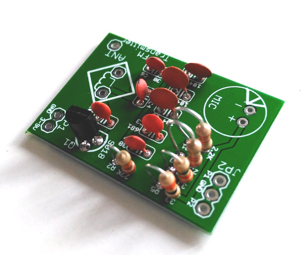
Assembly tutorial- FM transmitter DIY kit

If you have to come to this page directly from a search site, please go to this article first. This is the second article that gives  assembly instructions for FM transmitter kit. Please click here for the first article.

In this article, we will see how to assemble the FM transmitter DIY kit.

First of all, look at the schematic and PCB image given below.

FM TRANSMITTER DIY KIT (3) (more…)

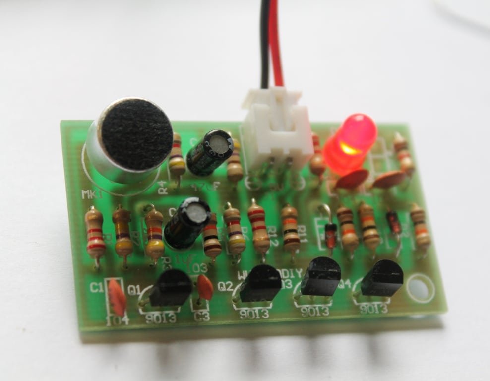
Simplest DIY clap switch- Assembly tutorial

If you have come to this page from a search engine, please check this article to know about clap switch. Follow the given steps to assemble the DIY clap switch.

Step 1:Collect all the required components for assembling the kit.

STEP 1

 Step 2: Read and confirm the specifications of the components.

STEP 2

Step 3: Insert all the resistors in its respective place according to its specifications.

sTEP 3

Step 4: Insert the ceramic capacitors into the board according to its labelled  specification.

STEP 4

Step 5: Insert the diode in its respective place.

STEP 5

Step 6: Insert the four transistors in the board.

STEP 6

Step 7: Place electrolytic capacitors according to its specification.

STEP 7

Step 8: Insert mic and LED into its place in the circuit board.

STEP 8

Step 9: Connect 2 pin JST connector in the circuit.

STEP 9

Step 10: Clap switch in action.

STEP 12

Video:

BC-216

100-240V AC Light Bulb Controllable FULLY Assembled Clap Switch

US $13.95
This FULLY ASSEMBLED sound/clap operated switch can be

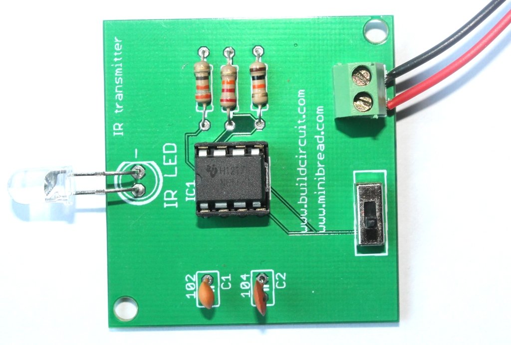
Assembly instructions for Infrared transmitter module

This article is about assembly of infrared transmitter used with digital object counter DIY kit. If you have come to this page directly from a search engine, please visit this page first to know about digital object counter. The suggested page gives you more details about this kit. You will eventually come back to this page, don’t worry 🙂 .

Check these articles for:

Assembly of IR transmitter kit is very straight forward and all components are through-hole. You can see the label and images printed on the circuit board and assemble the components accordingly. (more…)

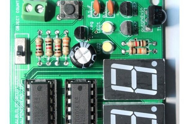
Digital object counter kit- Assembly tutorial

This article is about assembly of counter module used with digital object counter DIY kit. If you have come to this page directly from a search engine, please visit this page first to know about digital object counter. The suggested page gives you more details about this kit. You will eventually come back to this page, don’t worry 🙂 .

This kit includes everything you need to make a simple digital object counter. The object counter kit set includes an infrared (IR) transmitter DIY kit to make it work. The counter module and the infrared transmitter module can be kept at a distance of 1 meter with infrared LED facing towards the infrared sensor.  The LED continuously transmits infrared rays to the sensor and whenever an object obstructs the rays, the ‘seven segment display’ counts from 0 to 99. (more…)

Assembly instructions for Amarino 3.0 DIY shield

Step 13- Solder stackable header

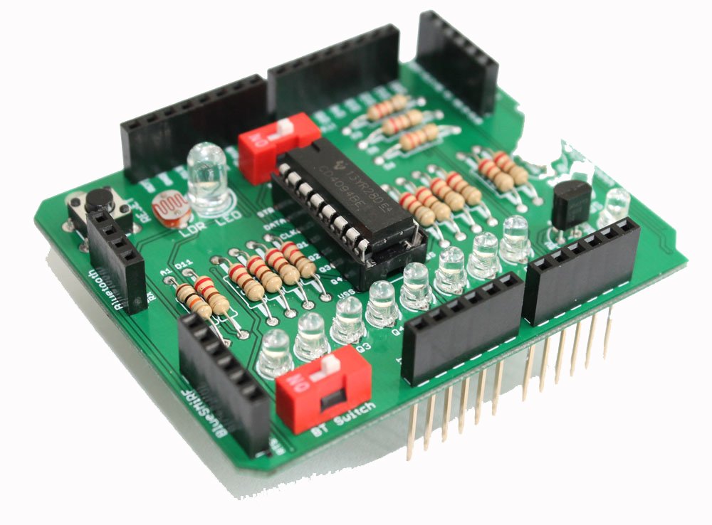
This post gives you the idea for assembling the Amarino shield. To get full details about this shield,  CLICK HERE.  When you buy the kit package, you will get the following PCB. The PCB clearly shows the pin and component names, so, it should help you to get idea of connections of components to Arduino.  For example, LDR is connected to A1 and RGB LED is connected is to D3, D5 and D6 and you can see those pins labeled on the PCB. (more…)

Search for products

Back to Top
Product has been added to your cart