Remote operated musical bell
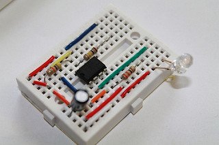
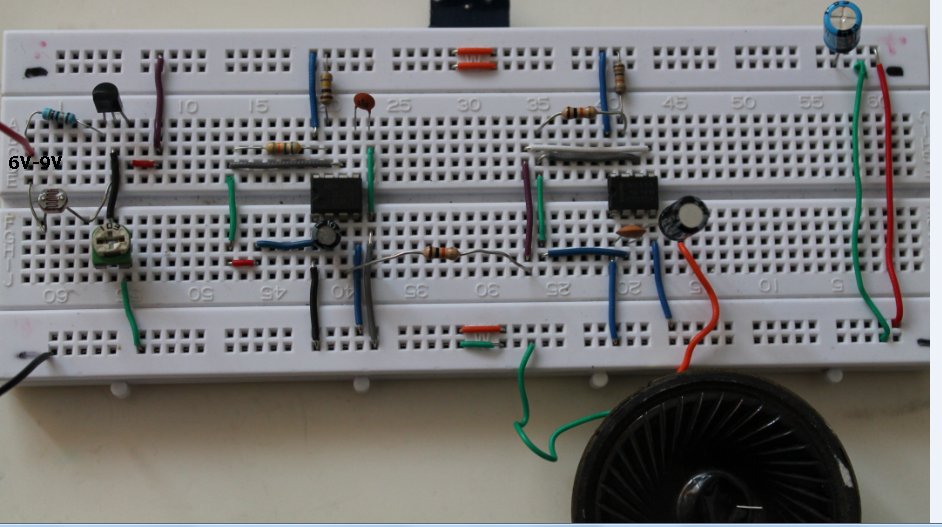
Remote operated musical bell can be made combining the following circuits.
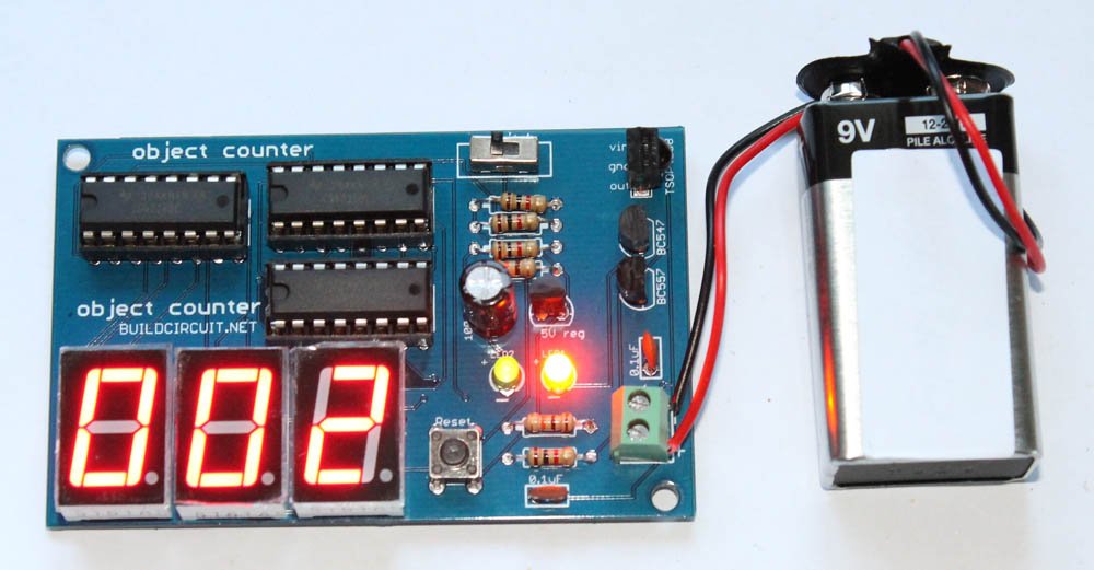
a) Remote tester
b) Basic RC circuit
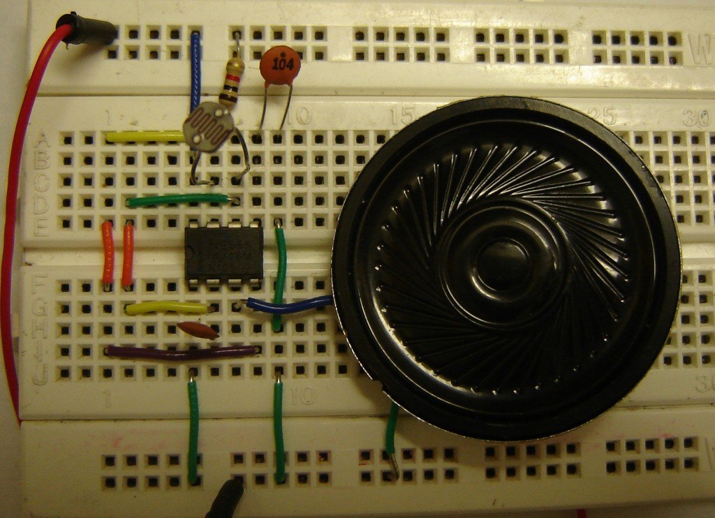
c) Simple Musical bell
When a remote is pressed, the circuit plays a music.
a) Remote tester

Remote operated musical bell can be made combining the following circuits.
a) Remote tester
b) Basic RC circuit
c) Simple Musical bell
When a remote is pressed, the circuit plays a music.
a) Remote tester

Description: Astable mode of 555 timer is used to generate pulses at regular interval. READ ABOUT ASTABLE MODE. The following schematic has been taken from buildcircuit.com. The following circuit can work as a music generator, Infrared transmitter and LED blinker depending upon the values of R1, R2 and C1. 🛠️ Dive into our collection of…

All of us know that NE555(or other versions) is a versatile IC for building big and small projects. Recently, I found some free simulators that would be very useful for electronics beginners. Please go the links I have given on this page and download those applications for FREE. You may also find something more useful…

Here’s a simple light activated police siren using light dependent resistor and NE555 timer. Before you make this project, I would recommend you to make the following projects. a. Light sensor and dark sensor I strongly recommend you to make a dark sensor and light sensor using LDR and understand clearly how it works. b….

An electret is a permanently charged dielectric. It is made by heating a ceramic material, placing it in a magnetic field then allowing it to cool while still in the magnetic field. It is the electrostatic equivalent of a permanent magnet. In the electret microphone a slice of this material is used as a part…

555 timer configured in monostable mode is a simple automatic dark sensor circuit that gives output when light falling on LDR is blocked.

This circuit has been configured in Astable mode. The output pulses are determined by the values of resistors R1, R2 and the timing capacitor C1. The formula for the frequency of pulses is: f= 1.44/[(R1+2R2)*C1].

One of the main objectives of LDR Engineering projects is to make students capable of developing their own logic for making devices. Here is an example that tells how LDR Engineering helps in developing ideas.

This 555 timer circuit below toggles the LED when a button is pressed. Pins 2 and 6, the threshold and trigger inputs, are held at 1/2 the supply voltage by the two 10K resistors.

This circuit has been configured in Astable mode. The output pulses are determined by the values of resistors R1, R2 and the timing capacitor C1. The formula for the frequency of pulses is: f= 1.44/[(R1+2R2)*C1].
The high and low time of each pulse can also be calculated.

Monostable mode of operation
Monostable mode of operation of 555 IC can be explained using a simple touch sensitive circuit. Here, timing constant (T) of monostable timer= 1.1*R1*C1. The following circuit has been configured in monostable mode. A monostable circuit produces a single pulse(for a certain duration determined by the Timing Constant(T)=1.1*R1*C1) when triggered at pin 2.