How to Change the Bluetooth 5.0 EQ Settings

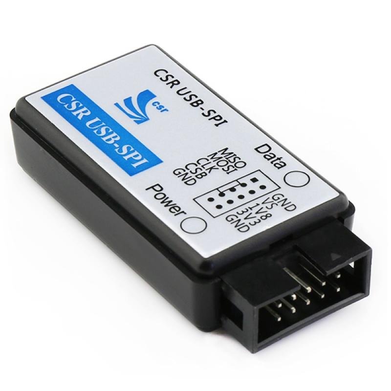
There is an in-built equalizer in Tinysine Bluetooth 5.0 module. If you have the CSR USB-SPI programmer, you can change the equalizer settings by yourself. TSA6175 module uses the CSR8675 Bluetooth chip. It needs a new version software to change the EQ settings. This tutorial will teach you how to set it.


Hardware and Software required:

Step 1:

Connect the CSR USB-SPI programmer and Tag-Connect line with an AudioB Plus convert board, then connect CSR USB-SPI to your computer by a mini USB cable, and windows will auto-detect it and install the drivers.

Step 2:

Connect TC2050-IDC-NL’s connector to the AudioB5 programming port. You need to locate the single steel alignment pin of the connector into the single hole of the PCB footprint, then press down softly to engage the spring-pin contacts. Make sure the first 6 pins have good contact with the corresponding pads. Then the blue LED and the red LED will flash alternately.


Step 3:

Let your smartphone get connected to the Bluetooth module and play the music. You can hear music out from the speakers. And then you can open the “CSRA64xxx Universal Front End” software.

Step4:

DSP->Connection. Select USB SPI and connect it.

Step5: Click “Monitor DSP” button.

Step6:

There are many settings that can be changed on the following page. Here we click “User PEQ” to enter the EQ value setting page.

Step 7:

In the settings page, Unclick the Flat option. Select “Bass Boost” in the Presets. Then click the “Apply” button. You will hear the Bass boost works immediately. You can also try other options.

Step 8:

Click “Download Params” to store the new settings to the Bluetooth module. Then you can remove the programmer and use the Bluetooth audio amplifier with new EQ values.

How to pair the remote with TSA1200

TSA1200 has a dedicated remote control, but if the remote control is broken or you want to use your own remote control, this tutorial will teach you how to pair.

Note: The remote control used must meet the carrier frequency of 38KHz and support the NEC standard.

Hardware and Software required:

  • audio amplifier board
  • connection cable

How to pair remotes

Step 1: Connect TSA1200 to the BVC port of the audio amplifier board. Power up the audio amplifier board using 12V DC power.

Step 2: VOL+ button pairing

1. Press and hold the VOL+ button of TSA1200.

2. After the yellow LED of TSA1200 flashes, press a button (marked as button A) on the remote control with the other hand for 2 seconds.

3. Release the VOL+ button when TSA1200 yellow LED flashes.


Step 3: Rewind button pairing

1. Press and hold the Rewind button of TSA1200.

2. After the yellow LED of TSA1200 flashes, press the button (named as button B) on the remote control with the other hand for 2 seconds.

3. Release the Rewind button when the TSA1200 yellow led flashes.


Step 4: Play/Pause button pairing

1. Press and hold the Play/Pause button of TSA1200.

2. After the yellow LED of TSA1200 flashes, press a button (named as button C) on the remote control with the other hand for 2 seconds.

3. Release the Play/Pause button when TSA1200 yellow LED flashes.


Step 5: Forward button pairing

1. Press and hold the Forward button of TSA1200.

2. After the yellow LED of TSA1200 flashes, press a button (named as button D) on the remote control with the other hand for 2 seconds.

3. Release the Forward button when TSA1200 yellow led flashes.


Step 6: VOL- button pairing

1. Press and hold VOL- button of TSA1200.

2. After the yellow LED of TSA1200 flashes, press a button (named as button E) on the remote control with the other hand for 2 seconds.

3. Release the VOL- button when TSA1200 yellow led flashes.


Step 7:

Press button A/B/C/D/E on the remote control. If the yellow LED on the TSA1200 is always on and the red LED is blinking, button pairing is successful. If the yellow LED flashes, the pairing has failed. You need to repeat the steps.

Note: You can choose any 5 buttons on the remote control to correspond to the 5 buttons on TSA1200. After the new remote control is successfully paired, the old remote control cannot control the TSA1200. If you want to use it, you need to re-pair.

BLUETERM ANDROID APPLICATION

VT-100 terminal emulator is a program for communicating with any serial device using a Bluetooth serial adapter. The RFCOMM/SPP protocol emulates serial communications over Bluetooth.

You need a Bluetooth serial adapter. (more…)

Enable Bluetooth Audio Amplifier Pin Code (Password)

Enable/Change The BT Pair number

All of our Bluetooth audio amplifier boards and Bluetooth audio receiver boards use AudioB plus module as the core bluetooth receiver module. The default bluetooth name is “BT SPEAKER”. Maybe you want change it to a special name or add a password to this module. We just updated the AudioB plus design and breakout the programming port. Here we will introduce how to enable and set the bluetooth module password.

Hardware and Software required:

Step 1: Connect the CSR USB-SPI programmer and Tag-Connect line with a AudioB Plus convert board, then connect CSR USB-SPI to your computer by a mini USB cable and windows will auto detect it and install the drivers.

Step 2: Connect TC2050-IDC-NL’s connector to AudioB plus programming port. You need to locate the single steel alignment pin of the connector into the single hole of the PCB footprint, then press down softly to engage the spring-pin contacts. Make sure the first 6 pins have a good contact with the corresponding pads. Then the blue led and red led will flashes alternately.


Step3: Make sure the connection is fine, then open PSTool in BlueSuite 2.5.0.

Step4:

Choose “SPI BCCMD”, and if the connection is fine, the CSR USB-SPI device will show in “Port”, then click “OK”.

Step5: change the password

Input “fixed” in “Filter”, then choose the option named “Fixed PIN”, the text box on the right will show the current password of Bluetooth module(default is “0030 0030 0030 0030”,That means the password is 0000), if you want to change it, just input the new password in this text box. For example, here we input “0035 0036 0037 0038” (password:5678))then click “Set” to complete the change.

Step 6: enable password

non-aptx AudioB plus module:

Input “local” in “Filter”, then choose the option named“Local supported features block”, the text box on the right will show the current parameter configuration of Bluetooth module(default is “ffff fe8f ffdb 875b” ,That means password disabled), if you want to enable password, Please change the last number to 7 ,That is “ffff fe8f ffdb 8757” then click “Set” and finally click “Reset&Close” to complete password settings and enable.

Aptx AudioB plus module:

Input “local” in “Filter”, then choose the option named“Local supported features block”, the text box on the right will show the current parameter configuration of Bluetooth module(default is “ffff fe8f ffdb 875b” ,That means password disabled), if you want to enable password, Please change them to “ffff fe8f ff9b 8753” then click “Set” and finally click “Reset&Close” to complete password settings and enable.


Turn on your phone’s Bluetooth and scan for new bluetooth devices.Your phone will search for the AudioB Plus module automatically. Usually, our AudioB Plus modules are named as “BT speaker”.

Click “BT speaker” to connect, and you need to input the new password :5678.Then click “OK” to connection to AudioB Plus.

Note:

1. If you haven’t installed CSR BlueSuite 2.5.0 on your computer, please download it here and install it. During the process of installation, you need to check the option “set debug transport the USB SPI”.

2. You may need to install the driver for CSR USB-SPI programmer on your computer.
For 32 bit system:

C:\Program Files\CSR\BlueSuite 2.5.0\drivers\win32
For 64 bit system:
C:\Program Files\CSR\BlueSuite 2.5.0\drivers\win64

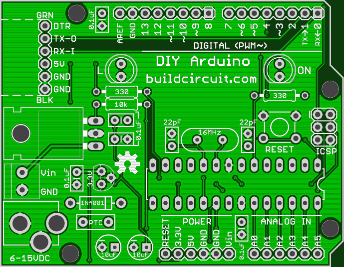
USB Boarduino Gerber and Eagle Files For Arduino enthusiasts

USB Boarduino is very much similar to DC boarduino. A USB boarduino board has a USB socket in place of DC barrel, that’s all. This product is no longer sold by Adafruit, so, we cannot get the description. However, if you want to order or redesign it, here are the files:

This is what we get from the gerber viewer: Overall, top and bottom views

Order PCB from one of the companies below:
Advertise with us


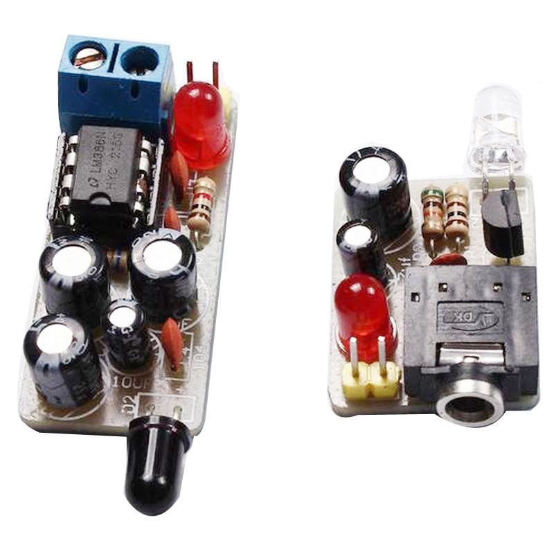
How to use infrared based music transmitter and receiver

This is a very interesting project for beginners. We had made similar project several years ago and published on BuildCircuit.COM. Check out this page. In this project, music from an audio source can be transmitted wirelessly via infrared medium.

There are two kits included in this package. One is transmitter and the other is a receiver.

On the transmitter side:

On the transmitter side, music is fed to the circuit and it is transmitted to infrared LED via an amplifying transistor so that the audio signals can be transmitted as infrared rays. If you connect a speaker in place of the infrared LED, the kit would work as a simple amplifier. (more…)

EasyEDA’s Gerber viewer for beginners and experts

logo2-200x56Few months ago, we had published an article about EasyEDA and described about its features. We see EasyEDA as one stop solution for all the PCB design and manufacturing processes. Check out the previous article about EasyEDA. 

EasyEDA has been providing most of the services related to PCB/circuit design and manufacturing to its customers. The only thing missing was a Gerber viewer which has also been fulfilled recently. Check out EasyEDA’s Gerber Viewer.

We recently tested its Gerber viewer and noticed some exciting features that are rarely available on other Gerber viewers. Here are the 4 points that make EasyEDA’s Gerber viewer a complete solution for visualizing the layers of PCB.

(more…)

How to use Micro USB 5V 1A Lithium Battery Charging Board/ Charger Module

Lithium battery charger (2)

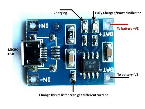
Here is a simple and a low cost Lithium Battery charging breakout board. This article is about the charger breakout board based on TP4056.

It uses a Micro USB for connecting the breakout board to any computer or ‘USB wall adapter’. It works with linear charging method. It offers 1000mA charge current by default but it is adjustable from 50mA to 1000mA by soldering a resistor. The default resistor soldered in on the board is 1.2K Ohm. A resistance and current table has been shown below on this page. (more…)

NeuroDreamer Sleep Mask

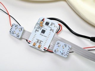
Use your brainwaves to help you rest, guided by soothing music and fading lights.” – The NeuroDreamer Sleep Mask by Cornfield Electronics is a meditation device that flashes colored lights at your eyelids and plays brainwave beats for your ears to help you fall asleep, have lucid dreams, or for meditation. NeuroDreamer is open source and CC-licensed and also designed by Adafruit friend Mitch Altman.

The NeuroDreamer is open source, so it can be fun to explore the schematic diagram while looking at the physical device. The main board has a Zilog Z8F083A 8 bit microcontroller, similar to but less expensive than an Arduino chip, important for reducing cost of bill of materials for manufacturing many thousands of units. (more…)

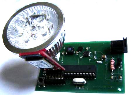
Thesis project- Ubiquitous computing based Smart phone controlled LED lighting system

Designed by: Sagar Sapkota (Contact)


(IT IS NOT A COMMERCIAL PRODUCT- PLEASE DON’T ASK FOR ITS DESIGN)

This is my Master’s degree thesis project. I did this project at the University of Turku, Finland. I completed this project in March 2012. The project was selected for an international conference organized in Japan.

smart phone controlled LED lighting (4)

Android phone application based on Amarino Platform

smart phone controlled LED lighting (3)

The smart phone controlled LED lamp

Features of the device:

1. Buck topology LED driver controllable with an Android smart phone. Dimming method: Pulse width modulation (PWM).

2. Communication medium used was Bluetooth.

3. ATmega328 Microcontroller was used in the device. It is based on Arduino and Amarino toolkit(for ubiquitous computing).

4. The LED driver responded automatically to inbuilt light sensor of Android phone.

5. Smart phone user interface displayed the temperature of the LED lamp and ambient light present in a room.

6. The driver responded to orientation sensor of the Android phone.

7. LED driver could be controlled with the phone user interface.

8. Dimming of the LED light was achieved by Pulse width modulation.

Watch the initial phase of the project. I built the project on a breadboard and tested a hand-made lamp using a serial emulator application.

Buck LED Driver using LM3404

The driver was built at home. The components were soldered with hand.

Amarino Experiment- Temperature sensor data and LED controller on Amarino Interface- redirected

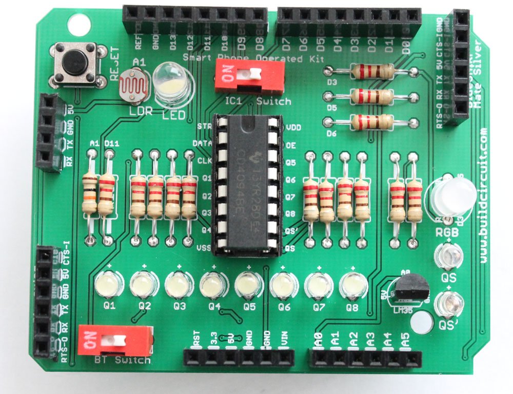
This experiment makes the use of ‘Android- Arduino BTCOMM Shield’ and Amarino. If you are not familiar with the shield, visit this page. 

This experiment is similar to my previous tutorial- Sensor graph and LED controller together.

You can also see one more similar experiment- Sensor graph and LED controller using Smart Phone- Arduino Shield.

If you have never worked with Amarino, I strongly recommend you to visit Amarino page and understand the basics of Amarino.

In this experiment, the sensor signal is fed to A0. Get the circuit layout of Amarino Shield

(more…)

Amarino Experiment- Sensor graph and LED controller- redirected

This experiment makes the use of  ‘Android- Arduino BTCOMM Shield’  and Amarino. If you are not familiar with the shield, visit this page. This experiment is similar to my previous tutorials Sensor Graph basic experiment and Sensor graph and LED controller together.

If you have never worked with Amarino, I strongly recommend you to visit Amarino page and understand the basics of Amarino. In this experiment, the sensor signal from LDR is fed to A1. You can also see A1 clearly on PCB.

(more…)

RGB Multicolor lamp using Amarino and Smart Phone- Arduino Shield- redirected

This experiment makes the use of  ‘Android- Arduino BTCOMM Shield’  and Amarino. If you are not familiar with the shield, visit this page. 

This experiment is similar to my previous tutorials on RGB multicolor lamp using Amarino. and RGB multicolor lamp with custom Bluetooth ID on Amarino Interface.

If you have never worked with Amarino, I strongly recommend you to visit Amarino page and understand the basics of Amarino.

(more…)

Search for products

Back to Top
Product has been added to your cart