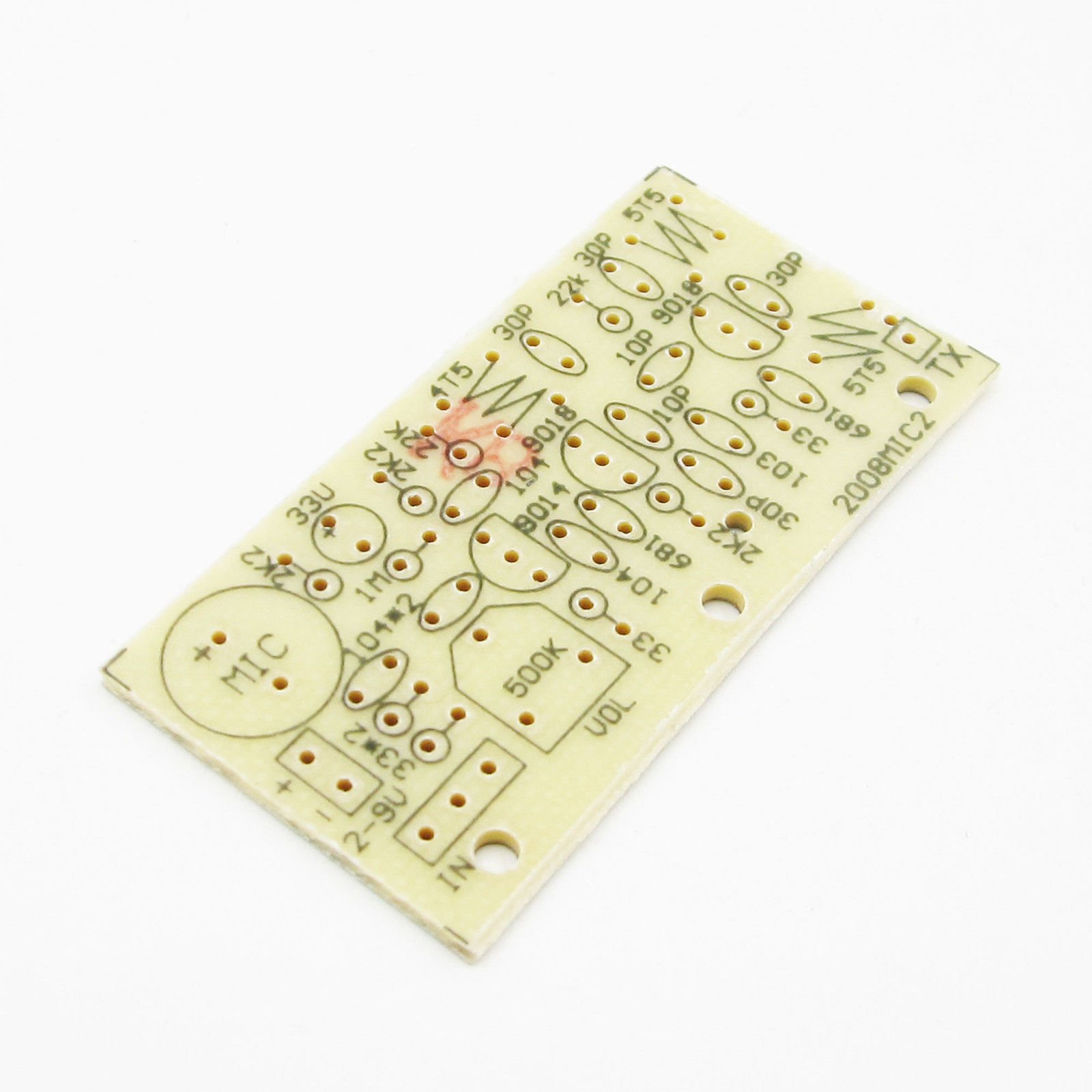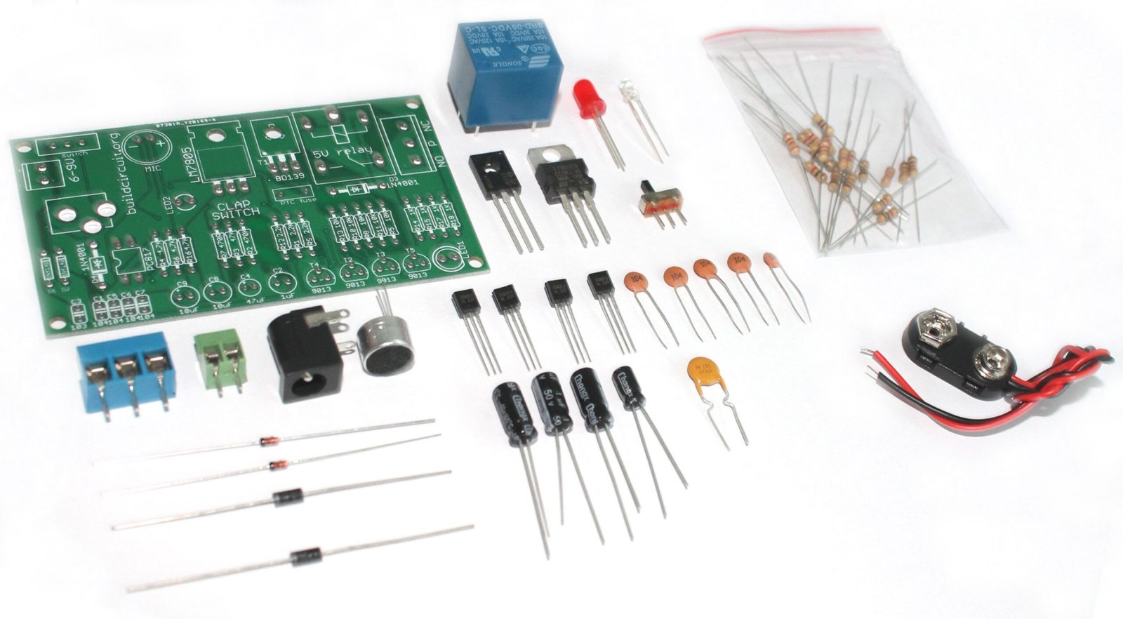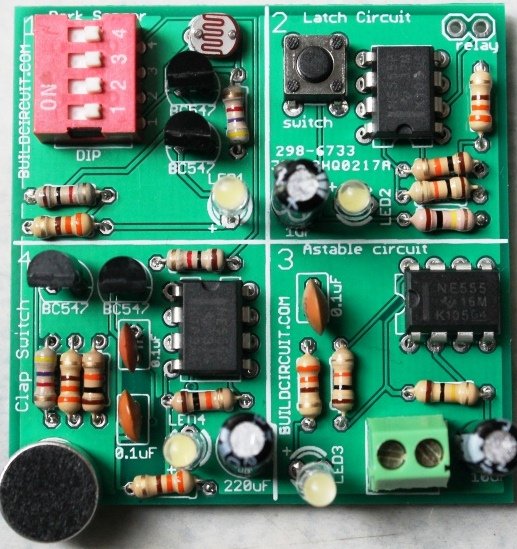
DIY KIT 44 – FM Transmitter DIY kit using 3 transistors

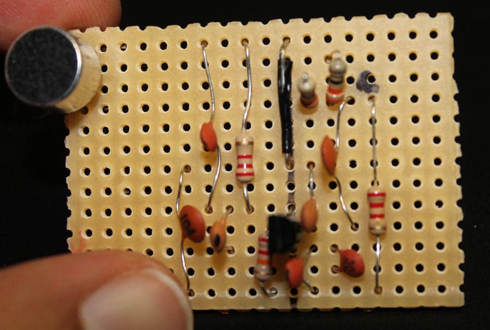
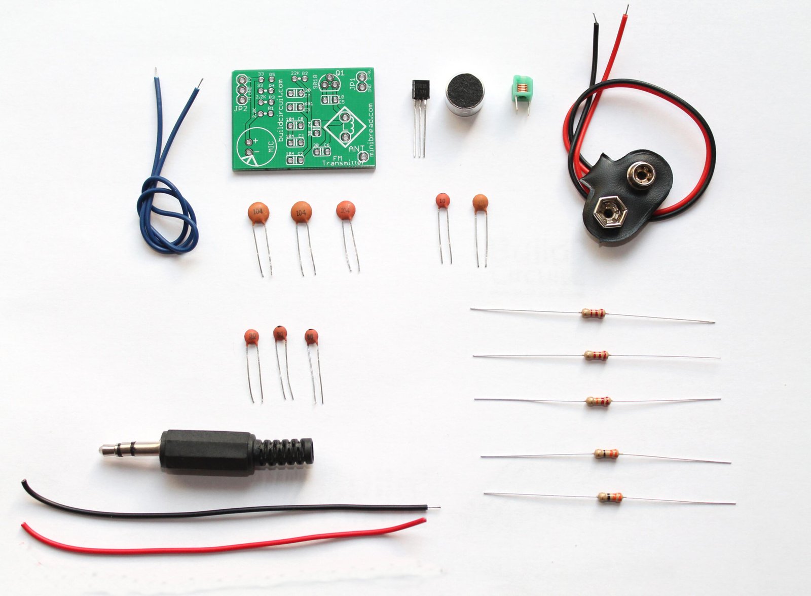
This is yet another FM transmitter DIY kit for beginners and hobbyists. It is slightly different from our previous FM transmitters. It has 3 NPN transistors and the transmission range is around 50-100 meters.

It is an enhanced wireless microphone with excellent transmission quality. The voice transmitted by the microphone can be heard using an ordinary FM radio. You can also transmit audio signals.

Frequency range: Around 83Mhz
Working voltage: 1.5V -9V
Range: More than 100 meters at 4.5V. For the general radio to receive the FM signal, users need to solder a 50cm wire to the kit.

The following is the schematic and working principle:

The electret microphone converts the voice to an audio signal, the C2 works as a coupling capacitor sending the signals to the base of Q1. The signal received at Q1 is supposed to be modulated. When there is a sound signal, the transistor junction capacitance changes and it eventually changes the oscillation frequency which we can call ‘frequency modulation’ (FM).

FM signal is then fed to the high-frequency tuning amplifier via C6. The tuning amplifier amplifies the signal and then, C12 and L3, as well as the wire antenna transmits the signals as high-frequency electromagnetic waves.

  • R1 is a bias resistance to electret microphone (MIC), generally selected in the range 2K-5.6K.
  • R4 is the collector resistance.
  • R5 is the base resistor, providing a bias current to Q1.
  • R7, R8, C5, L1, C8, and C7 together form a high-frequency oscillation circuit.
  • R7 to the Q2 base to provide bias resistance.
  • C5 and L1 make the oscillation circuit.
  • Q3, R9, R10, L2, C10, C11 constitute the high-frequency power amplifier circuit.
  • C8 is the feedback capacitor to the transistor Q2.
  • R8 works for the stability of the Q2 DC operating point.
  • C7 is the capacitor for grounding distorted AC signals.
  • R9 to the power transistor Q3 to provide the base current.
  • C10 and L2 together work as a tuning circuit and the oscillation circuit C5 and L1  also tune at the same frequency to get the maximum output power so that the transmitter can transmit the electromagnetic signals as far as possible.

Check out the following images for assembly tips. You can see all the images on Flickr also. 

Check out the other images of the kit

One mistake: Step 1: There are 3 x 2.2K and 2 x 22K resistors. Not 5 x 2.2K resistors. Sorry for this mistake


How to use the fully assembled clap switch

DIY CLAP SWITCH

We are now selling fully assembled CLAP SWITCH(shipped from Sydney, Australia). Click here to visit the product page. 

If you have come to this page from a search engine, we recommend you to visit the page about DIY clap switch. In this article, we are going to describe how you can use the “do-it-yourself(DIY) clap switch” to light up 100-240V appliances. When we say 100-240V appliance used with a clap switch, it is usually a bulb/lamp/CFL(Compact Fluorescent Lamp) tube. This article is for absolute beginners, so, we will try to explain all the small details. (more…)

5 beginners projects that work in the first attempt

Just started electronics ? And you don’t know any engineering behind your projects and you are afraid of failure ? Then, this article can help you get started in electronics.

Usually, success in initial projects plays important role in electronics amateurs and engineering students’ career. Many students quit electronics because they fail in their first, second projects. After few failures, student keep a misconception that electronic projects working now might not work later. Thus, I recommend beginners to start with those projects which will work in their first attempt and give inspiration from your own work.

(more…)

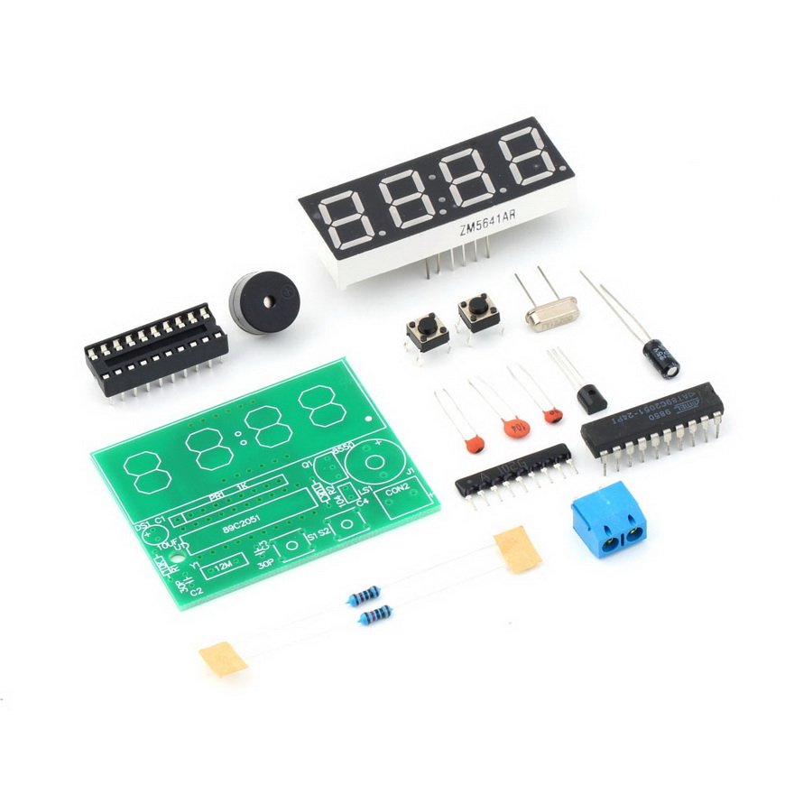
How to use C51 4 Bits Digital Electronic Clock DIY Kit

This is a very popular digital click for beginners. It is a DIY Kit. It is now available at BuildCircuit Store. It is based on AT89C2051-24PU.

Basic Functions:

1. Hour and minute display & minute and second display

2. Two alarms set up

There is a buzzer that works as an alarm. When the clock reaches hours…like 1:00, 12:00, etc., it will beep for 3 times. The alarm beep is optional, you can disable it.

(more…)

The simplest and the cheapest FM transmitter- Do-it-yourself(DIY) kit for amateurs

Here’s one of the easiest, simplest and the most popular FM transmitter for amateurs and electronics beginners. With this DIY kit, you can transmit your voice or audio over an ordinary FM radio within the FM broadcast band. It is a DIY kit designed by Sagar Sapkota. You can buy this kit from BuildCircuit Store. The best thing about this transmitter is that you don’t have to make your own inductor for this kit. Making an inductor is bit hard for amateurs. Besides, this kit is not only capable of transmitting voice using microphone but also transmitting music from your music player. (more…)

Digital object counter DIY kit

We are now selling CD4026 and CD4029 up and down counter modules.

This kit is based on my previous tutorial on ‘digital object counter‘. I had published the tutorial under ‘minibread’ category. Please check the tutorial. 

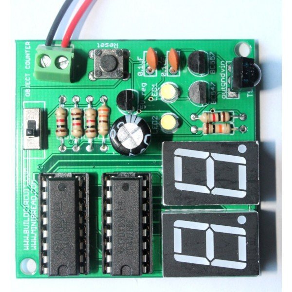
IMG_0673

Digital object counter

In that tutorial, you can see that there is only one seven segment display and there is no reset switch. Well, that was extremely basic circuit.

What’s new?

Digital object counter

My new DIY digital object counter works with TSOP4838 infrared receiver   and there are two seven segment displays displaying numbers from 0 to 99.   An IR transmitter is oriented towards the TSOP4838 infrared receiver of counter module and objects are moved between the counter and transmitter modules. Each time an object passes between the two modules, the seven segment displays show increment in numbers. The counter module can be reset to 0 at any time and restart the counting.

Watch the video below:

The counter can be reset to 0 by pressing the reset switch(see on video). The counter stops counting if the IR rays is continuously falling on the IR sensor. As soon as an object obstructs the IR signal, the counter immediately counts the interruption.

The distance between the counter module and the IR transmitter should be around 1 meter.

The module can also be tested with general remote control. Thus, you can also call it as a simple remote tester. For each press on your remote control, there is increment in number.

Power supply: The counter works with a 9V battery and the IR transmitter works from 6V to 9V.

Counter operating with a remote control:

Schematic of counter module:

Counter

When TSOP4838 infrared receiver receives infrared signal, it triggers BC557 and switches on LED2. This trigger also charges the RC circuit network made up of C1(100uF), R3(1K) and R4(1K) and switches on the transistor BC547 for a few seconds. Transistor Q1 switches on the LED1 and gives clock signal to IC1(CD4026). For each clock, CD4026 drives the seven segment display and increases the numbers on the display.

Pin number 5 of IC1 is connected to pin 1 of IC2 for chaining the two CD4026 chips. For adding one more digit, the pin 5 of IC2 should be connected to pin 1 of IC3.

Schematic of IR transmitter module:

IR transmitter schematic

GO TO IR TRANSMITTER ASSEMBLY INSTRUCTIONS PAGE

IR transmitter is based on astable mode of 555 timer. The 555 timer, resistors and capacitor on the transmitter module output IR rays at 37.974Khz(approximately 38Khz). The TSOP4838 infrared module operates at 38KHz infrared frequency, however, that is not so strict with these kinds of basic experiments. It actually operates at frequencies between 30Khz to 40Khz.

Use astable mode frequency calculator for finding out the frequency of 555 timer. While using the online calculator, enter R1=18K, R2=10K and C1= 0.001uF, you will get 37.974 KHz.

How to use the kit

Place the two kits facing each other in a straight line. The IR receiver(on the counter module) and the IR LED(on the transmitter module) can be kept in a line of sight(straight line). When you move an object in between the two kits, the counter module counts the number of interruptions in the line of sight.

Behavior 1: When you place the IR receiver and the IR LED in a straight line, the two 3mm LEDs on the counter module are switched on and it counts as soon as there is an object in the line of sight.

Object counter

Behavior 2: When you place the IR receiver and the IR LED close to each other but not in a straight line, the two 3mm LEDs on the counter module are switched off and the counter counts as soon as an object moves away from the line of sight.

Slide2

Please watch the following video to be more clear:

Other related tutorials:


BC-3014A

3 Digit Digital Objects Counter With Laser Module

13.7518.34
This is 3 digits digital object counter kit

Check out all the counters

COU-18

1.8" Photoresistor And Laser Operated Medium Digital Objects Counter

22.94
This is an upgraded version of the previous
SCO-23

2.3" Common Anode Seven Segment Display Driver

18.34
COU-902

2.3" common cathode seven segment display driver

13.7518.34
This is a CD4026 based up counter driver

CD4026- 1 Digit Up Counter Module

4.55
  • It works as an UP counter. You can
Sold out
COU-23

Photoresistor And Laser Operated Large Digital Objects Counter With 2.3" Displays

27.54
A laser light module illuminates the photoresistor continuously

DIY Arduino Kit- How to Make your own Arduino UNO

Do-it-yourself-DIY-Arduino (3)

We are now selling BLUE colored DIY Arduino kit.  

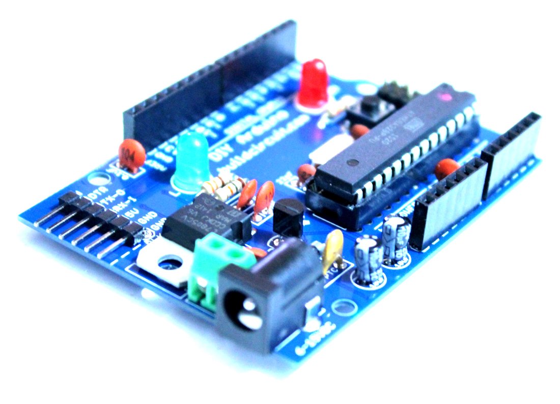
You know that there are several versions of Arduino hardware. Hobbyists have also made Arduinos on strip boards giving different looks. Here’s one more Arduino, that is a simple do-it-yourself (DIY) kit. It is just like any other Arduino UNO board. However, it does not have FT232RL chip, therefore, you would need a separate FTDI basic module to burn your sketch.

This kit contains everything you need to build your very own Uno-compatible DIY Arduino board. Simply follow the Assembly Guide and after some basic soldering, you’ll have made a fully-functional Arduino-compatible development board. The included ATmega328 comes pre-loaded with the “Optiboot” bootloader so you don’t have to worry about loading the firmware, simply solder it together, connect an FTDI Basic and load your favorite sketch using the Arduino IDE.

After the board is assembled, it can be powered by an FTDI connection or a regulated 6-15VDC power supply connected to either the DC Barrel jack or the 2 pin screw terminal.

Note: You will need either an FTDI Basic or FTDI cable to load code using the Arduino IDE.

diy arduino

Kit Includes:

  • 1 x Arduino-Compatible plated through holes (PTH) Kit PCB
  • 1 x ATMega328 with Optiboot bootloader
  • 1 x L78L33 3.3V Voltage Regulator
  • 1 x 5mm Green LED
  • 1 x 5mm Red LED
  • 2 x 330Ohm Resistor
  • 1 x 10kOhm Resistor
  • 1 x 16MHz Crystal
  • 2 x 22pF Ceramic Capacitors
  • 5 x 0.1uF Ceramic Capacitors
  • 2 x 10uF Electrolytic Capacitors
  • 1 x LM7805 5V Regulator
  • 1 x Diode 1N4001
  • 1 x Resettable Fuse PTC (300mA)
  • 1 x 28-Pin DIP Socket (To seat your ATMega)
  • 1 x Push Button Reset Switch
  • 2 x 6-Pin Female Headers
  • 2 x 8-Pin Female Headers
  • 1 x 6-Pin Right Angle Header (To connect your FTDI Basic)
  • 1 x 0.1uF Capacitor
  • 1 x DC Barrel Jack
  • 1 x 2-pin screw terminal
  • 1 x 6 pin ICSP header

Assembly video tutorial: 

Documents:

You can purchase this kit from here:

BC-2138

Do-It-Yourself (DIY) Arduino- Make Your Own Arduino

13.75
This kit contains everything you need to build

How to change BT module audio gains and Hands Free Settings

Change The BT module audio gains

All of our Bluetooth audio amplifier boards and Bluetooth audio receiver boards use AudioB plus module as the core bluetooth receiver module. If you have to use a mismatch speakers or power supply in your system(size limit or other reasons). You may want limit the maximum output audio gains to avoid the distortion on high volume. All our amplifier boards have a programming port on it. You can change the BT Audio gains by yourself.

Change hands free settings.

The bluetooth module default settings is hands free enabled. When your smartphone connected with the bluetooth amplifier. If you have a phone call come in. It will ring loud through the speakers. Some users don’t like it. You can change this settings by yourself.

Hardware and Software required:


Step1:

Connect the CSR USB-SPI programmer and Tag-Connect line with a AudioB Plus convert board, then connect CSR USB-SPI to your computer by a mini USB cable and windows will auto detect it and install the drivers.

Step2:

Connect TC2050-IDC-NL’s connector to AudioB plus programming port. You need to locate the single steel alignment pin of the connector into the single hole of the PCB footprint, then press down softly to engage the spring-pin contacts. Make sure the first 6 pins have a good contact with the corresponding pads. Then the blue led and red led will flashes alternately.


Change The BT module audio gains:

Step3:
Make sure the connection is fine, then open Config Tool.Click “Open From Device “,then Make sure that the values of the “Default A2DP Volume Level” and the “Default Volume Level “ options are all values of HFP15. If not, please modify to HFP15.

Step4:
Select “Audio Gains ” tab, There are “Speak Gain(dB)” and “A2DP Gain(dB)” settings in this page. Here we only need change the “A2DP Gain(dB)” values. If you use an iPhone, You can find there are 15 volume levels on iOS system(Android are different). HFP1 is the start level audio volume, HFP15 is maximum audio volume, If you want limit the maximum audio volume. Just adjusting the corresponding HFP gain values.


Step5:

After the modification is completed, click on the right side of the “Write Device”. The module settings changed after reboot.


Change hands free settings.

Step3:
Make sure the connection is fine, then open Config Tool.Click “Open From Device “, HFP features tab->uncheck the HFP,HSP and WBS option.

Step4:

After the modification is completed, click on the right side of the “Write Device”. The module settings changed after reboot.

How to assemble a line following robot – Page 2

See page 1

Remaining part of assembly of line following robot…

Fix the nut bolt set on the PCB

Solder the photo resistor/LDR as shown on the image.Make sure that the LDR is at least 5mm above the ground or spot where you are placing the robot.

Solder the transparent 5mm LEDs. The LEDs should be 5mm above the LDR.

Peel of the top sticker to stick the included battery holder

Pass the wires through the hole

And solder it as shown below

The package includes two wheels also.

Fix the wheels to the motors

This is how you insert the holes of the wheel to the motor

Use the screws to tighten the wheel to the motor

The line following robot is now ready. Make sure that you use a different switch as shown below

Make a track with a black insulating tape. You may use paint or permanent marker. I have one with a black insulating tape. Watch the following video:

How to assemble a line following robot – Page 1

The assembly of a line following robot is pretty straight forward. If you follow the silkscreen labels, you will be able to assemble it easily.

The line following robot comes with the components as shown on the image.

Start with resistors

Solder all the resistors that comes with the package.

Solder the transistors S8550

Solder the 5mm red LED. Make sure that the Anode and Cathode go into the right holes.


Solder the 100uF capacitors.

Solder the variable resistor 10K ohm

Solder 8 pin DIL socket

Solder wires on robot motors

Peel off the sticker and stick the motors

After sticking the motors, the robot should like this:

Make sure that the motors are soldered on the PCB solder pad.

See the remaining part of this tutorial on the next page.

Adafruit Ultimate GPS module for Aduino – 66 channel w/10 Hz

This is an original Ultimate GPS module from Adafruit

The features of the this ultimate GPS module are:

  • -165 dBm sensitivity, 10 Hz updates, 66 channels
  • Works with 5V and 20mA
  • Breadboard friendly + two mounting holes
  • RTC battery-compatible- it is not included
  • Built-in datalogging
  • PPS output on fix
  • Internal patch antenna + u.FL connector for external active antenna
  • Fix status LED

This GPS module has been designed around the MTK3339 chipset, and this high quality GPS module can track up to 22 satellites on 66 channels. It has a high-sensitivity receiver (-165 dB tracking!) and a built in antenna.

It can make up to 10 location updates a second for high speed, high sensitivity logging or tracking. Power consumption is incredibly low, consumes only 20 mA during navigation.

There are some extra features which can be used later if you ever want it: a ultra-low dropout 3.3V regulator so you can power it with 3.3-5VDC supply, 5V level safe inputs. There is an ENABLE pin which can be used to turn off the module using any microcontroller pin or switch. There is a footprint for optional CD1220 that keep the RTC active and makes warm start and turns on tiny bright red LED.

The LED blinks at a frequency of 1Hz when it’s searching the satellites and blinks once every 15 seconds when a satellite is found to conserve power. If you want to have an LED on all the time, the module provides the FIX signal out on a pin so you can put an external LED on.

The two features that really stand out about this ultimate GPS module are:

  1. External antenna functionality
  2. The built in data-logging capability.

About external antenna functionality:

The module has a standard ceramic patch antenna that gives it -165 dB sensitivity.If you want to have a bigger antenna, you can snap on any 3V active GPS antenna via the uFL connector. The GPS module will automatically detect the active antenna and switch over to the new one!

About Data logging capability:

The other important feature of this module is the data logging capability that Adafruit team has tested successfully. Since there is a microcontroller inside the module, with some empty FLASH memory, the newest firmware now allows sending commands to do internal logging to that FLASH. To achieve that, you need to have the microcontroller send the “Start Logging” command.

After the microcontroller sends the command, it can go to SLEEP mode and it can remain silent (it does not need to talk to the GPS). This save a lot of power. The time, date, longitude, latitude, and height is logged every 15 seconds and only when the GPS module finds a satellite.

The internal FLASH is capable of storing about 16 hours of data, it will save data even if the power is lost. It is not possible to change what is logged because it is hardcoded into the module

Technical details:

  • Satellites: 22 tracking, 66 searching
  • Update rate: 1 to 10 Hz
  • Position Accuracy: < 3 meters (all GPS technology has about 3m accuracy)
  • Velocity Accuracy: 0.1 meters/s
  • Warm/cold start: 34 seconds
  • Acquisition sensitivity: -145 dBm
  • Tracking sensitivity: -165 dBm
  • Maximum Velocity: 515m/s
  • Vin range: 3.0-5.5VDC
  • MTK3339 Operating current: 25mA tracking, 20 mA current draw during navigation
  • Patch Antenna Size: 15mm x 15mm x 4mm
  • Output: NMEA 0183, 9600 baud default
  • DGPS/WAAS/EGNOS supported
  • FCC E911 compliance and AGPS support (Offline mode : EPO valid up to 14 days )
  • Up to 210 PRN channels
  • Jammer detection and reduction
  • Multi-path detection and compensation

You can buy this Audio amplifier at BuildCircuit.COM.AU. We are official distributor for Adafruit.com

buy-now-button-300x51

2 x 8 Watt Bluetooth Stereo Audio Amplifier Board – TSA2110B (TWS/Apt-X)

This is a 2x8W audio amplifier board integrated with Bluetooth 4.2 . It has perfect class-D architecture (based on TPA3110D2) and every channel has 8W power output. This board can be powered by any DC 8V-16V power supply. It can be used to drive any 4Ω or 8Ω passive speakers. The highlight point is Apt-X and TWS supported. Therefore, users can stream audio to 2 pairs amplifier boards at the same time wirelessly. (more…)

2 x 8 Watt Bluetooth Audio Amplifier Kit – TSA2210

This kit is designed for amplifier manufacturer and DIY users. A volume knob, weatherproof panel mount LED and a TSA2210 amplifier board is included in this kit. Users can adjust the Bluetooth audio volume either on the smartphone or turning the real knob physically. You can power this kit with a 12V DC power supply or a 12V batttery. The LED indicates the ON/OFF state and the battery voltage state. User can install this kit in a box easily and make their own audio amplifier product. (more…)

Assembly Tutorial of Amarino Nano 1.0

Amarino Nano 1.0

Please visit this page first to know about Amarino Nano.

Assembly process of this kit is very easy. If you have basic soldering knowledge, you can assemble the board within half an hour.

You can directly visit BuildCircuit’s Flickr page and see all the assembly steps.

If you look at the PCB, you will see that the silkscreen labels are enough to guide you to solder the components properly.

PCB

Before you start, make sure that you have all the required components.

Here’s the list of components:

  • 1 x Arduino Nano
  • 1 x Bluetooth adapter
  • 1 x Amarino Nano PCB
  • 2 x 15 pin female headers
  • 1 x 4 pin female header
  • 1 x Red Color 1P DIP switch
  • 1 x LM35DZ temperature sensor
  • 1 x 5mm LED
  • 1 x RGB LED- common cathode
  • 1 x photo resistor
  • 4 x 220 Ohm resistor
  • 1 x 10K Ohm resistor

Now, follow these steps:

1. Always start with the small components. So, solder all the resistors first. Solder 220 Ohm resistors.

Step 2- Solder resistor that connects to D11

2. Solder 10K Ohm resistor and the photo resistor

Step 3- Solder 10K Ohm resistor

3. Solder LM35DZ temperature sensor.

Step 5- Solder LM35

4. Solder 1P DIP switch, the one in RED color. This switch has to be turned off while uploading the Arduino sketch.

Step 6- Solder 1P DIP switch

5. Solder 5mm white LED

Step 7- Solder 5mm LED

6. Solder common cathode RGB LED

Step 8- Solder RGB LED Step 8.2- RGB LED top view

7. Solder 4 pin female header for Bluetooth moduleStep 9- Solder 4pin female header

8. Solder 2pcs 15 pin female header to stack the Arduino NanoStep 10- Solder 15 pin female headers

9. Stack the Bluetooth module and the Arduino Nano on the correct female headers. Your Amarino Nano board is ready to use. Visit this page for experiments.

Step 11- Fix Arduino Nano and Bluetooth Module

10. Connect a mini USB cable to operate the kit.

Connect USB cable and use the kit

See the following links:

1. About Amarino Nano 1.0

2. Experiments with Amarino Nano 1.0– You will get all the Apps and Arduino sketches on this page.

3. All the images on Flickr


Where can you buy this kit ?

The kit is available at BuildCircuit Store (www.buildcircuit.com.au- Free Shipping in Australia)

Amarino Nano-1-1Buy now button

Search for products

Back to Top
Product has been added to your cart