


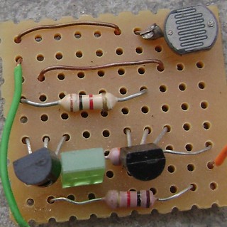
Dark/Light sensor using transistor

Automatic dark detector senses darkness. As the light level decreases and LDR meets the maximum threshold resistance, the circuit automatically switches on the LED D1.

Dark sensor with variable resistor:
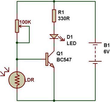
A dark detector can be made using a variable resistor. The sensitivity of the circuit can be adjusted with a variable resistor.
High resistance-> more darkness to switch on the LED.
Low resistance-> less darkness to switch on the LED.
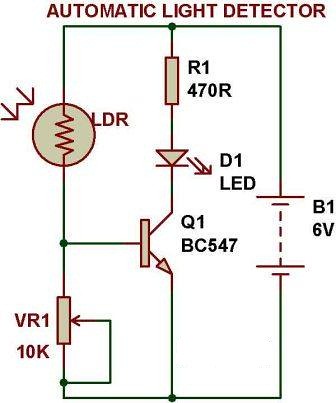
Automatic Light detector using variable resistor
A light detector senses light. As the light level increases and LDR meets the lowest threshold resistance, the circuit automatically turns on the LED D1. We can adjust the sensitivity using the preset VR1-10K.
LESS RESISTANCE(VR1)-> LESS DARKNESS TO SWITCH OFF THE LED
HIGH RESISTANCE(VR1)-> MORE DARKNESS TO SWITCH OFF THE LED
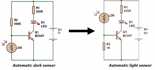
Just swap the resistor and LDR to convert a dark sensor to a light sensor
🛠️ Dive into our collection of DIY Kits, 🔊 Audio Amplifiers, Digital Scoreboards, FM transmitters, and more!
🎶 Explore endless possibilities at our new store.


this website has helped me a lot with my course work.
Hi i have a 4 kw solar pv system and i am looking to buy/build a dark/light sensor switch to use as a switch, in line, into the domestic supply to turn on and off an electric oil filled radiator rated 1 or 2 kw, when the solar panels are generating enough power to run the heater. So I don’t have use energy from the grid..
Can anyone help?
Today, I want to make automatic switch, to turn on my car head lamp based on this dark sensor. Is this your scheme can be recommended for that?
Actually, I’ve done this experiment from your scheme. With a relay (instead of LED), I hope my plan worked.
Apparently, I have problems; at the time of the light intensity changes gradually (in the afternoon), or at the time of the transistor base current for the process began to get saturation, relay shaking, of course, my bulb flashes great, even broken.
Do you have any suggestions to solve this problem?
Thanks & Regards,
amdani
Yes, i do have solution for this problem, if you make 741 based dark sensor, the relay does not shake or flicker/flutter. You can get the circuit here: http://www.ldrengineering.org/dark-sensor-using-741/
Please wait till 29.1.2011 so that I can make it an show you on video. Please ask if you have other questions.
I try to click the link for dark sensor using 741 but is unavailable. My relay flickers. Help. Thanx
Thank you very much for your quick response.
I will soon try the circuit.
If I use a 12 volt battery, what components need to be changed?
Thanks & Regards,
amdani
I want to make a dark sensor that turns on 1 led when it is dark, another when the light is ambient, and one final led when it is bright. I havent been able to find any circuit based on this description on the internet and I wanted to know if I could get some pointers.
If it isnt possible, im okay with that! I just want to know if it is possible in one setup or if I need to make 3 sensors operate 3 individual LEDs, and if I can; could I be led to a link of the circuit? Im aming for something small and something I can enjoy making for myself.
i wanna circuit to glow 100w bulb in dark senser with the help of DC voltage.
Well, you can do that using a relay. It is quite simple. see this example: http://www.ldrengineering.org/how-to-use-a-relay/
This page gives you the idea for using a relay and using 100W(AC bulb) operating with a DC based dark sensor. Be careful while using 220V AC.
hi there – great little circuit and easy instructions, thanks!
thnx i will try it inshaallah
i want to make a lamp for my aquarium with dark sensor. i want to use 6 white leds 5mm..can u pls post a diagram for me to follow. thanks
thnx i will try it inshaallah gr8
can you show me a digrame of how i can make a automatic dark detector 12v dc using a led tail light thank you and god bless
i want to make a sensor siren using LDR .can u sent me a diagram please.
MY Group make this project…..<3<3
Sir…can i make a color sensor composed of red, green, blue, yellow, and orange.
Can i use these LDR’s to make a color sensor like these?
And can u help me make a schematic diagram on these.
Thankz You…
Thanks, after a long search…this is the most complete DIY exist. I could successfully done both L/D sensor.. 🙂
Hi, I want to build a circuit that will turn a small motor in one direction when light is present and then reverse the motor when the light is out.
This circuit will be used to open a door in the morning when the sun comes up. After the door is completely open, it will trigger a limit switch to stop the motor. When darkness falls, the motor will need to run in reverse to close the door. When the door is closed, it will also need to trigger a limit switch to stop the motor.
Is this possible? Thank you!
can you make the dark sensor work with the joule thief?
tanx a lot………..
Thanks man! It is surely the most simple and the best explanation for a dark/light sensor! I want to light up more than one, say 3 LEDs in this way. Any changes to be done? Thanks in advance buddy!! 🙂
If you are keeping 3 LEDs in Parallel, then, use another transistor, for example, BD139. and if you are keeping LEDs in series, you don’t need to make change. I recommend for series.
Should I use a 9V battery or let it remain the same?
keep 9V
Can please tell me the pin configuration in details of BC547…Please
Hi my brother, i am very impressed with your site. Can you help me with how to use ldr with atleast 40 leds for security lights
You need to use a dedicated “LED driver” and a microcontroller for controlling at least 40 LEDs or, you need to have a power transistor that can take up to 2 Amp.
hye mr admin..can u help me how to make dark sensor using relay..the relay must Normally Open when connected with 5WATT Solar Panel (Max. Voltage: 17V, Short Circuit Current: 0.34Ampere.)..Tq..What type of relay i need to use for this low power solar panel for switch the relay..
I am using the same configuration but using lm741 as comparator. The output of that will light an LED strip. I want to usr RC circuit to fade in and out that. What type of transistor do I need? Can you draw a schem. Thanks
hi sir, i need a theoretical proof for the values of the resistors used in this two circuits. this is quite a useful start for the beginners! nice job sir! help me out as soon as you can!
I want to know what is the resistance of a LDR in the dark and the risistance in the light..can any one tell me???????????
hi very nice video but can you till me is the same if i uesing 2N3904 Transistor
OR WHAT type i can use for this
Thanx alot.can u help me with acircuit diagram for adark sensor do
dear sir i currently saw your video on light sensor on youtube , i need to make this for my project so kindly can u give me the materials required to make it as i am unable to figure out the materials in video
Thanks!
You can see the components required on the schematic.
WHAT CAN WE USE INSTEAD OF A 330 OHM RESISTOR ?
PLEASE HELP ! 🙁
🙂 THANKS
you can use any resistor between 220 Ohm to 1Kilo Ohm
sir pls give me a ckt of light/dark sensor using opamp-LM358….in urgnt need for it….pls help me out sir…
check this> http://www.buildcircuit.com/experiment-with-lm358/
thnx for d link sir!!!
i made d ckt using LM358 n it’s functioning properly…but sir, dere’s 1 thng i wanna tell u that
even a 5th grade boy wud do d connectns if v gave him some basic tips n ckt diagram, but
being a future engg 1 shud know y is this happening….dis thot haunts me a lot…
thr4 1 request u if u can tell me d working of dis ckt…..i tried to figure out bt got
confused in no. of points…. i wud b very thnkful to u sir….
PLS help me out…
You need to learn about operational amplifier. You can start with LM741 operational amplifier(op amp). Try to understand the description of this project: http://www.buildcircuit.com/dark-sensor-using-741-2/
If you understand this you can also understand the working LM358 because it is also a type of op amp. The simple circuits have been published on buildcircuit for electronic starters. If you are studying in school, just focus on learning about components. There are several things you need to learn, so wait till you join engineering.
sir i want to generate emf of south and north pole in coil using operational amplifier lm393
and also want to generate emf in a coil circuit of 2 volt
i’m supposed to make a simple darkness activated alarm using a power of 6v..can you help me out?
Nice post. I was checking continuously this blog
and I’m impressed! Extremely useful information particularly the last part 🙂 I care for such info a lot. I was seeking this certain info for a long time. Thank you and best of luck.
Sir, i am a beginner in electronics and i am going to make this but i wanted to light up more LEDs instead of just one…so should i use a resistor of lower resistance and if yes then where should i place it or should i use a trim pot or potentiometer?? please help
Nevermind sir i saw the comments and figured it out but please help on this thing that if i connect my LEDs in series will not their brightness decrease and if yes then please recommend a solution..
need some pointer here. I’m building an automatic light system which need to be shutoff during night time. i believe i have some idea on that part using simple connection through a relay. however i’ve to depend a car battery. so my question is how do i size up the circuit so it can take up higher amp and volts. thanks in advance.
Can i use 100 ohms resistor for 100k resistor
no
not working?why
sir i need dark detector without bread board
Hey, can I use SL100 instead of BC547?
Also, I saw a couple of links that showed making the same thing using two transistors? One transistor will do right?
yes one transistor will also work. you can use SL100 also.
if i use greater or less than 6V battery will it work? why different resistors are used?
You can use any voltage that doesent burn out your LED. Remember V=IR so you may want to increase your resistance.
The Differant resisters adjust the sensativity of the phototransistor so if you change those values it may always stay on, or need very bright light.
It would also be smart to incorperate hysterisis so you dont get flickering when the current is “just” right.
i have made a automatic light sensor .if i use greater or less than 6V battery will it work? why different resistors are used?
sir,
hw to use this circuit with 12V DC and use 3-5 LED, plz reply me soon
Sir,
can I run this project with 12V DC, and want to use 3-5 LED(Big size) use as emergency light.
hai can u help me how can i use only one calculator as my counter and decounter
what should I do if I want to use 220VAC power (for Automatic Light Sensor function)?
add a relay to the output with a protection diode in front of the relay or search for connecting a relay on google and you will understand better.
sir this video is very helpful bt pls sir i wnt the working of dark sensor today only as soon as possible … as tomorw is my practical nd i hve made this circuit nd it is now working bt i dont know how it is working…. thank you sir
what would happen if i use 1k ohm resistance instead of 100k ohm? please reply ASAP
check yourself. or check here: http://www.buildcircuit.com/voltage-divider-rule/
thanks sir, i finally made it. the video tutorial was really helpful. great site! thumbs up!
also, if i connect collector and emitter in opposite way you have connected?
It does not work that way.
How to combine the dark and light sensor
i have connected emitter n collector in opposite way n it works why?
Which transistor to put if i want to run a DC motor instead of a LED.?? reply fast pls… imp
……
Use a mosfet IRFZ44 or 2n3055 based on the current rating of motor.
sir..
i follow your circuit in the video,but it doesn’t work..
i also do the automatic dark detector circuit on the breadboard but replace the transistor with 2N3904/BC547..
But,it work reversely..the led turns off when dark..
can u help me how to do it properly?
Maybe the terminals at the end of the breadboard are not connected..
We try it also and it doesn’t work. But after we troubleshoot it, we saw the ends are not connected.
It’s cause the transistor. Try to put B,E,C correctly.
Very good circuit !!!! Really helped me in my first project!!!!
Hi, I would like to ask why transistor is needed for lighting up the LED? Since LDR has almost similar characteristics as a variable resistor, through voltage divider rules, LED still turned on, right? Hope to receive your feedback. Thanks.
You could possibly have a fixed or perhaps the
adjustable form.
Dear sir,
How many bulbs or lamps can the above dark light detector control?Can it be modified to handle strong lamps?If yes help me with materials used thanks
can i use a 9v battery instead of a 6v power supply
sir
can i use a 9v battery instead of a 6v power supply
yeah..i..build..it
if i connect a buzzer in series with led …will it work…mean…b/w led and transistor i give a connection to buzzer…plz reply its urgent…..
Hi i wanna circuit to glow 100w bulb in dark sensor with the help of AC voltage. i want to use transistor instead relay.
Thank’s so much!!
your tutorial is the best!!!
Important data. Lucky myself I found your website by accident, for dismayed precisely why this coincidence couldn’t occurred in advance! I actually added the item.
Hi…. In this dark sensor circuit .. i want to illuminate the led using AC supply and not the dc voltage…. Can anyone help me out with this
ne555 ic and a 100k pot also work right?
I want to run a 9v motor instead of a LED in the Dark Sensor. can you please send me the materials wanted?
pleeeeeeeeeeeeease!!!!!
Can i use 1.2k resistance or 0.6 k ..?? My circuit is not working
Dark/Light sensor using transistor | BUILD CIRCUIT
air max de nike http://www.aguasdealcala.es/zapatillas/air-max-de-nike.html
First of all I wanna thank you. This circuit is really working fine. But, instead of led, i wanna replace that with 5v DC motor. I replaced BC547 with 2n3055. But it is not providing sufficient current to drive motor. Should I use SL100 ? Could you please help me out with this ?
Thank You,
You could use the darligton pair transistor BC517 to fire 2N3055 which would in turn drive the load.
That should work fine for your motor.
I want to make an dark detecting sensor. I want to make some changes like in place of led I want a buzzer. How to choose a good buzzer??? It’s for my school project to make security system
Do you have to use a breadboard to build a darkness detecting sensor
In my dark sensor light was on always I don know I am using your circuit why light is on
RE: Solar Panel Controller ‘Shut Off/Turn On’ Photosensor
SITUATION: Solar Panel Controller doesn’t function properly after the Sun comes up.
BACKGROUND: At a remote mountain location, I have a solar panel array to provide electrical power. It works well. However several lines of PWM controller units all have the same problem. When the Sun comes up the next morning, the controllers ‘misbehave’. Instead of reading 14V going into the battery array, they read 24V and the batteries don’t charge. They drain. When I disconnect the controller from the panels and reconnect it, then it works just fine.
The panel array provides 100W at 12V.
SOLUTION: Get a photocell switch that disconnects the controller from the panels after Sunset and reconnects after Sunrise.
PROBLEM: There is no such beastie on the market. They are all DUSK-TO-DAWN. No such critter as a DAWN-TO-DUSK.
CONCLUSION: I have to DIY.
This site’s article provides me with the basic information I need. But not being a Double-E major [I’m Microbio] I’m having to educate myself.
QUESTIONS: For this situation:
[1] What resistor is necessary for R1 470R?
[2] What resistor is necessary for the VR1 10K?
[3] What transistor is necessary to Q1 BC 547?