


Clap switch
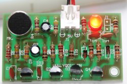
In order to make a clap switch, we have to combine the touch sensor(monostable mode of 555 and the transistorized dark sensor circuits. Whenever there is loud sound produced near the electret condenser mic, pin 2 of 555 gets triggered and it switches on the LED D1. The LED remains on for a definite time determined by R1 and C1. We can adjust the sensitivity of the circuit using a variable resistor in place of fixed resistor R5. You can check the circuit with 1K or 10K.
The schematic of clap switch:

You can purchase this kit at BuildCircuit
You can see the steps for making a clap switch on the video given below.
Please check the following video tutorial
")
")
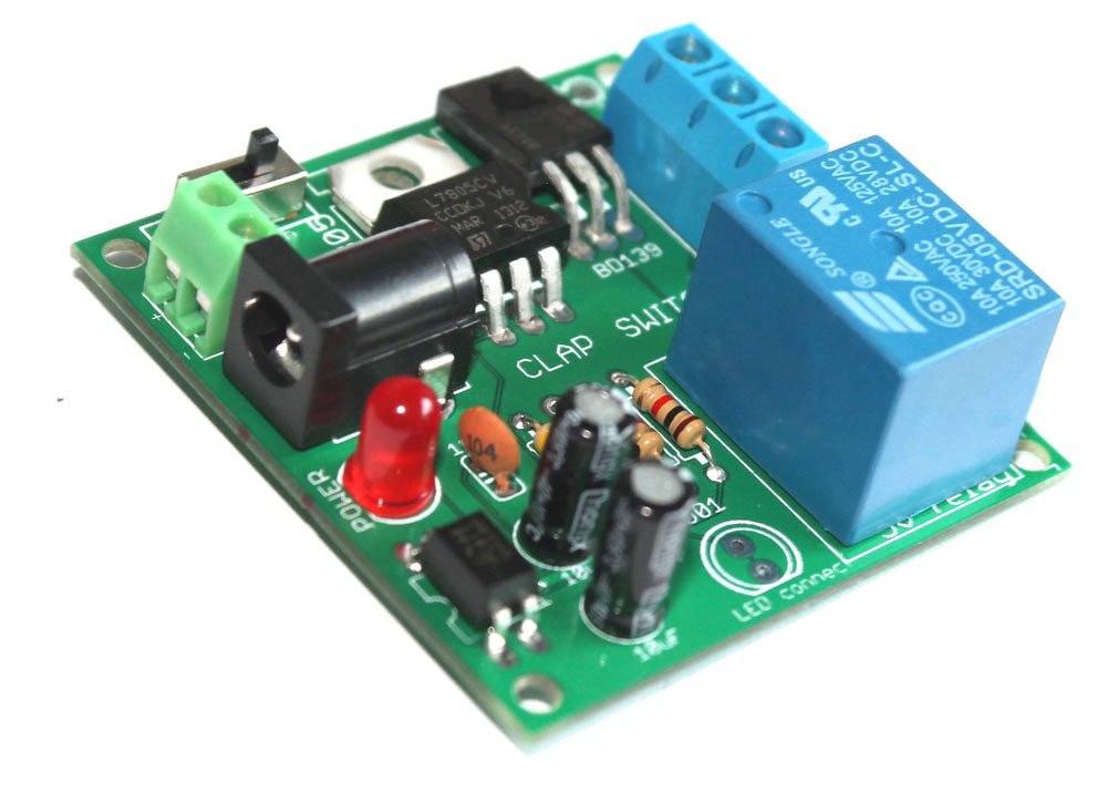
If you want to glow a bulb operating at 220V, use the following schematic:

Before you make this project, read carefully about RELAYS: http://www.buildcircuit.com/how-to-use-a-relay/ If you are not confident at making circuits, don’t work with 220V, it can be dangerous and harm you.
Related projects:
BuildCircuit is now selling a fully assembled clap switch that can operate 220V lamps. The first clap keeps the lamp on and the second clap keeps it off.
🛠️ Dive into our collection of DIY Kits, 🔊 Audio Amplifiers, Digital Scoreboards, FM transmitters, and more!
🎶 Explore endless possibilities at our new store.


very nice. i will try but it will not perform
were i buy a electret condenser mic? is that like a mic ok a pc?
Very cool! I have tried, and it worked very well :D, thanks for showing!
Realy good ; i was in search of it since a long time.Thanks a lot
is this on/off circuit for clap switch???
no. it just switches on LED for a definite time.
please gie me values of resistors
give me values please
You can see the values from the schematic.
how to download this vedio
You can download this video using a Youtube Video downloader, for example: http://www.youtubedownloader.org/
very nice i have applied in my bed room for swith off and on table lamp
thanks buddy for uploading such a innovative vedio
please help me with its pcb lay-out because i want to try it as my project
Hello, do you have a pcb layout for this one?
Thanks a lot.
Just wondering, is it a 24V power supply?
And, how can I make it possible to lit up multiple LEDs?
Thanks. (:
No, you can use 6V-9V power supply. You can glow multiple LED also. You need to know how to calculate current and voltage for many LEDs. You can calculate here: http://led.linear1.org/led.wiz
what’s the voltage of the 100uF capacitor? Thanks
You can use 10V to 25V, that means capacitors rated, 100uF/10V or 100uF/16V or 100uF/25V. But your power supply should be 6V-9V only. If you are using power supply more than 9V, then, use capacitors rated 16V or 25V.
what alternative can i used if 100uf is not available?
you can use 10uF, 1000uF and any other also. But use electrolytic capacitor only.
Thanks….I have another questions… Are the resistors’ wattage is 1/4 watts? And this 100N capacitor, is it equal to 104 ceramic capacitor? Thanks in advance.
Yes, the wattage is 1/4 watts. and the capacitor 100nF is 104. Actually, the capacitor code works like this: 104= 10 0000pF=10 and 4 zerospF= 100nF= 0.1uF. You can see other capacitor codes from here: http://drakedev.com/pic/capacitors.php
Thanks a lot!
I am done making this circuit and it worked… But how can I reconstruct it to operate on a 220 V output? Do you have a schematic diagram for this kind of circuit? Thanks.
I have just attached a new schematic for operating bulb at 220V. Before you read about this project, I recommend you to read about relays. read from here: http://www.ldrengineering.org/how-to-use-a-relay/
After you completely know about relay, then only work with 220V, otherwise, it can be dangerous. be careful and best of luck. keep on commenting.
Do you have a video or a picture of that circuit?
No, I don’t have. But you can visit http://www.ldrengineering.org/how-to-use-a-relay/ to know about relay. there are pictures about connecting relay in the circuit.
Okay… I’ll try to build this..
Can a breadboard carry this circuit?
Yes, you can try it on breadboard. There won’t be any problem, I am sure. but, if you are working with 220V, be careful.
Does the 220V circuit turn on and turn off by means of claps unlike the DC-supplied one w/c turns off automatically after few seconds?
220V circuit turns off automatically after few seconds. If you want to make it keep it turned off or on, then you should merge a toggle switch with clap switch. You can get the idea of making a toggle switch from here:
http://www.ldrengineering.org/toggle-switch/
I recommend you to make a light operated switch first so that you can understand how this toggle switch works. Link is here: http://www.ldrengineering.org/light-operated-switch-2/
In the LIGHT OPERATED SWITCH CIRCUIT, replace LDR with the condensor microhone used in clap switch and adjust sensitivity with the VR1- 10K resistor connected from the base of transistor Q2 to ground.
When you adjust this 10K resistor, it will be more or less sensitive to your clap. I am sure that, when you clap, this circuit will switch on the LED till you don’t give another clap and vice versa. After making this project, replace the LED with a relay to glow 220V bulb. again visit: http://www.ldrengineering.org/how-to-use-a-relay/ to get the idea of using a relay.
After you understand this project, try the same concept on the original clap switch circuit. For this week, please try this project. If you cannot make it, I will show you after a week, but please don’t forget to remind me. best of luck.
What I have to do to increase the turn off- time of the 220V circuit?
The same question. 🙂
Do you have a schematic of the 220V on/off clap switch? ty
check out this: http://www.ldrengineering.org/clap-switch/clap-switch-2_ldr_engineering-2/ . click on the figure to enlarge it.
read more about it on this page: http://www.ldrengineering.org/clap-switch/
The turn on and turn off time depend upon the resistor R3 and the Capacitor C2 of 555 timer. time on= 1.1xR3xC2. Therefore change the values of R3 and C2 and see the change in on time. To know more about monostable mode of 555 timer, see here: http://www.ldrengineering.org/modes-of-ne555-monostable-and-astable/
I have tried the first circuit and it worked. But when I tested it several times, it had stopped working well. When I clapped, it turned on but did not turn off. It began to blink and when I tried to clap again, it turned off and on while blinking and ticking….
Can you post a diagram of the 220V Clap on-off switch? TY
I have tried the first circuilt, the one that is operated by 6V battery and it worked. But when I tested for several times, it did not work well. When I clapped, it turned on but never turned off. Then it began to blink. I clapped once again and it turned off and on while blinking and ticking even I’ve tested in a silent place. I also tried to used another timer.
just wanna ask. will it matter if we use 10V relay instead of 6V stated in ur schematic?
If you use 10V relay, then power supply should be above 10V . 6V relay is OK for 6V, 9V or 12V power supply.
As you can see that my schematic has 6V power supply, it cannot run/drive 10V relay, so, it does not work with the given schematic. In order to make it run with 10V relay, change the power supply to 10V-12V. It works with 12V also.
So, first change your power supply to 12V then connect you 10V relay. I hope this helps you. best of luck
hi, a question. If i want to add more LEDs where do i put them and if i want the LEDs to switch off when i make a sound rather then waiting for them to off on its own how do i do that?
You will have to do some calculations and add a transistor because if you add more LEDs, the voltage and current levels will change. Besides, if you want to turn off immediately, follow this instruction:
If you want to make it keep it turned off or on, then you should merge a toggle switch with clap switch. You can get the idea of making a toggle switch from here:
http://www.ldrengineering.org/toggle-switch/
I recommend you to make a light operated switch first so that you can understand how this toggle switch works. Link is here: http://www.ldrengineering.org/light-operated-switch-2/
In the LIGHT OPERATED SWITCH CIRCUIT, replace LDR with the condensor microhone used in clap switch and adjust sensitivity with the VR1- 10K resistor connected from the base of transistor Q2 to ground.
When you adjust this 10K resistor, it will be more or less sensitive to your clap. I am sure that, when you clap, this circuit will switch on the LED till you don’t give another clap and vice versa. After making this project, replace the LED with a relay to glow 220V bulb. again visit: http://www.ldrengineering.org/how-to-use-a-relay/ to get the idea of using a relay.
After you understand this project, try the same concept on the original clap switch circuit. For this week, please try this project. If you cannot make it, I will show you after a week, but please don’t forget to remind me. best of luck.
hi, me again i did like you said by replacing the LDR with a condenser microphone but the only thing that happens is the relay clicking and i need to tap the microphone only then will the relay click, clapping or snapping my fingers wont make it click. hope you can help me again.
Hi Sagar. Let me tell you that this proyect works perfectly, I just want to ask you one question: How can I do more amplification in order I can clap for a far distance and activate the bulb?
Thanks in advance!
Hello friend, I want answer the first question first, AMPLIFICATION: If you mean sensitivity, then, change the value of resistance R5. In the schematic, there is 4.7K, now you change it to 1K or 300Ohm or 10K and see the change, the sensitivity changes, which means that the LED switches on from far or near.
Regarding your second question, I have already given the schematic on the same page, see below the clap switch page, there is another schematic with the name, CLAP switch GLOWING 220V bulb. Before you make a circuit glowing 220V bulb, learn about relay, otherwise, it can be dangerous. To use a relay, read this article:http://www.ldrengineering.org/how-to-use-a-relay/
i have a question.. i done the connection but when i connected it to the 6v supply, the led just turn on for a seconds then it turn off. it just like that. if i make sound(clap) led didnt light up., i checked again the connection and nothings wrong about it. i just followed the video.. then when i connect it again to the supply (6v) the same thing happened.. the led just turn on then off.
Your microphone might not be working. just check it once. You need to have at least 2 extra microphones while doing this project. These microphones are very sensitive to heat, so, you mic must have been broken while soldering. Please try again. In the same page, I have shown about how to connect such microphone.
another question. which is better to use? a 1/2 w resistor or a 1/4 w resistor???
Use 1/4 Watt resistor. When there is no additional information about watt, you should understand that it means 1/4 watt.
hi, i’m italian,i don’t speak very well english..:) can i have the PCB of this beautiful project,please!? 🙂
Sorry, I don’t have PCB now. But I can make and send you later.
what is the function of transistor circuit in the diagram?
The transistors together work as switch. the main function of the transistor is to amplify current.
we can use another type of microphone instead of condenser mic ,or not?
Yes, you can use it.
I have a question, what should I do for the LED to remain lit on till i clap again.. ?
should i remove the cap, replace with another component, using the clap-switch schematic with the 555 timer.
What should I do ?
Thanx in advance.
Please read other comments. I have explained about this several times. If you want to make it keep it turned off or on, then you should merge a toggle switch with clap switch. You can get the idea of making a toggle switch from here:
http://www.ldrengineering.org/toggle-switch/
I recommend you to make a light operated switch first so that you can understand how this toggle switch works. Link is here: http://www.ldrengineering.org/light-operated-switch-2/
In the LIGHT OPERATED SWITCH CIRCUIT, replace LDR with the condensor microhone used in clap switch and adjust sensitivity with the VR1- 10K resistor connected from the base of transistor Q2 to ground.
When you adjust this 10K resistor, it will be more or less sensitive to your clap. I am sure that, when you clap, this circuit will switch on the LED till you don’t give another clap and vice versa. After making this project, replace the LED with a relay to glow 220V bulb. again visit: http://www.ldrengineering.org/how-to-use-a-relay/ to get the idea of using a relay.
After you understand this project, try the same concept on the original clap switch circuit. For this week, please try this project. If you cannot make it, I will show you after a week, but please don’t forget to remind me. best of luck.
IT’S VERY NICE AND WONDERFUL.
very nice
How much does a condenser mic cost in india……………….any idea plz help me???
Must be around Rs. 10-15, even cheaper
can yu post any charger with auto cut off
Please check out this link: http://www.electronicsforu.com/electronicsforu/lab/ad.asp?url=www.electronicsforu.com/electronicsforu/circuitarchives/view_article.asp?sno=240&title=Auto%20Turn-Off%20Battery%20Charger
Charger with auto turn off
how much this project cost …..
If you are from India, it costs less than 50 rupees.
thanx ….
can i connect the transistor switch circuit to hold on the lamp ….
NO…..It will need a relay to turn on the circuit
no that auto turn off circuit s taking more i need circuit 10v input and output 6v or 7v 500ma …. thanx advance …
i tried this project but when connect the battery the condesar mic get heat rapidly kindly heil plz ………..
which battery are you using : 9V or 4AA cells connected in series to give 6V
i used ne555 ic and transistors are bc547b plz help me plz ……
Plz help .. Replay me plz ..
Thanx a lot its work well .. Thanx a lot ..
You should not connect an electret microphone to the base of the transistor. It needs a 4k7 to 10k resistor in series with the microphone.
why not?!?!it is not required to connect any other resistor as there is no resistance required between microphone and base of transistor…..
i like this circuit…
Hoe much will cost for meking this project in India??/
Please help me…..
less than Rs. 30
No it did not cost less than Rs. 30 as the mic itself is now a rare component and that’s why it cost around Rs. 10 and the 555 IC is also around Rs. 5 ……..so it will take about 50 to 60 rupees
Can you please help me…and tell me where to get the materials for this project..i really need this for my science day!!. 🙂
If you are from India, you can buy the components from your local electronic store, I am sure that you can get from there. In case if you don’t find microphone, take out from a useless telephone. I am sure it also works.
Hi
I built this several times and I cannot get the circuit to work. I checked my connections over and over. I’m using two 3904 transistor instead of the BC547 and I’m using a 9volt battery. I rebuilt the circuit from the 555 timer down, and everything from the 555 timer works. But when I test the circuit from the 3904 transistors nothing. Please help…I really need this project to work. I also need to use 9volts, the circuit needs to power something using 9 volts.
Will
I just made another clap switch using 2N3904. It works well. Please checkout here:http://www.buildcircuit.com/combine-two-dark-sensors-and-make-an-easy-clap-switch/
What if i need to do this for my room..and my room is pretty large..so what should be my setting so that i can turn the light on with a clap..easy!
Also can you give me a list of items needed..as i could not fid that anywhere~!
AWESOME PROJECT….but i am having a problem with the circuit that this circuit switches the relay without any sound given to mic after five to 6 minutes and also holds the relay for a very long time sometimes..plz reply me on this
Please do that project in modules. Please follow the steps from this tutorial: http://www.buildcircuit.com/combine-two-dark-sensors-and-make-an-easy-clap-switch/
if it still doesn’t work, I will help you.
ive mounted this exact circuit shown in the video about six to seven times now and not once has the led illuminated in my attempts…ive changed the microphones thice in these attempts…please help
Please follow clap switch circuit described on this page: http://www.buildcircuit.com/combine-two-dark-sensors-and-make-an-easy-clap-switch/
It’s always good to break a big project into small modules, make separately and join them together. In this project also, I have shown how to make a clap switch integrating two dark sensors made from transistors and 555 timer.
thanks i got it working…but again it doesnt work consistently!also what steps should i take if i wish to mount it on a copper clad pcb??please reply asap
connect mic directly to the transistor ..instead of shorting it using connecting wire!!
SIR CAN I USE BC548 INSTEAD OF BC546?PLEASE RPLY ME ASAP …
Yes. You can use BC547/548/549 for your project.
can u please give me the full details of voltage across every point?????
Please measure using multimeter. We don’t measure voltage across all points because there are several projects in this website. I hope you understand.
can i use 9v battery for this circuit???is this work for circuit??
Yes you may
good simple and efficient
hello sir am new in electronics can i know if i can use any NPN on this curcuit please?? can i use 2n2222 am from mauritius can’t get BC547/548/549 and what’s the voltage do i need for the capacitors (Q1;Q2,Q3) can i use (C1,C2,C3 10v please please!!!always i stuck on capacitor voltage is it necessary??anyone can reply me please HELP ME
Hello friend, The project should work with any kind of NPN transistor, it should also work with 2N2222. You can also try with 2N3904 or BD139 or any other. And regarding capacitor voltage, if you are using 6V power supply, use any capacitor with rating more than 6V. the point is, the voltage rating of capacitor should be greater than the power supply voltage. So, you can use any capacitor with rating above 6V, for example, you can use 10V, 25V, 50V, 100V, etc.
If you are using 12V power supply, please use capacitor with 25V rating. I hope this helps.
thanks alot SIR i will try this curcuit!!the second one is it clap on clap off curcuit 250 volts??
I’ve tried this several times and followed every step, but whenever I connect the battery, the led turn on and stays on even without clapping. What might be causing the problem? PLEASE HELP!
If it does not work, please try this: http://www.buildcircuit.com/combine-two-dark-sensors-and-make-an-easy-clap-switch/
AND try this: http://www.buildcircuit.com/clap-switch-using-3-different-modules/
Try to make the circuit in modules, please follow the instructions carefully. Best of luck.
hi am japhet and am final year student in one of the polytechnics existing in my country and it happen that my lecturer ask me to carry out my project on a clap operated switch and honestly speaking i need and urgent help please i want to know the function of each transistor.capacitor,resistor,condenser mic,rely,bread board and the source voltage help me please thank U as U do so.
Hello, for understanding the working of clap switch, please read this post: http://www.buildcircuit.com/clap-switch-using-3-different-modules/
and go to different modules pages and try to understand the project in modules. Follow the instructions exactly. for example, make dark sensor first and understand it. Then, make a monostable mode 555 timer, understand it, then finally combine those two project and replace LDR with microphone. If you read all the projects, you will understand the working of all the components.
Dear Sir,
I am trying to build a clap operated switch for 220 Volts A.C supply.
As the schematic is given above, it is given for 6 Volts D.C power supply. But if I will use 9 Volts D.C power supply then what should be the values of other components? (say resistors, capacitors, diodes & transistors)
Even if you are using 9V, you don’t need to change ratings of other components.
Thanks a lot sir….
Can I use Batery 9v for circuit: http://www.youtube.com/watch?feature=player_embedded&v=TeDHWHRVpm8
??????????
dear sir i dont hav 47k registor available in near by market can u plzz suggest me any other if i can use instead 47k ??
yes, you can use any resistor close to that value, say 56k or you can also put 22k+22k in series.
Hello I was wondering if you could help me with this :
How would I go about trying to change this circuit so that the clap switch activates a small motor for a very brief period of time and not a LED?
Thanks (:
If you are using just a simple motor, then just remove LED and put motor in place of that.
At first the circuit did not work. I replaced the BC547 transistors with 2N2222. you also do need thw electret mic which you can buy at Jaycar. The circuit work when you make a loud clap or whistle close to the mic.
I enjoyed building it and have learnt something about the working of circuits.
The best part for me isto do the research when the circuit does not work.
Awesome little circuit.
sir i have made it on smaller bread board it seems from the video that i have used smaller breadboard do u have any solution
sir please reply fast one time i have made it its not working please tell me any solution i have to submit tommorow do u have any other video of clapping switch usin gmicrophone so please post it and tell me solution its seems that microphone is not working how can nthis be possible please tell me fast
hello sir,
in that clap operated relay circuit, THAT RELAY IS A 6V DC. wHEN THE RESISTORS ARE PARARAL OHMS VALUE REDUCE 50% OK. 100 PARAREL 100 = 50.. THAT WAY 12V DC RELAY CAN I USE WITH THE PARAREL RESISTOR?…
IF CAN WHIC H VALUE RESISTOR CAN I PARAREL WITH MY 12V DC RELAY.
THANKS..
Since the power supply is 6V, you should use 6V relay. Try 12 V power supply for 12 V relay.
good…..
that actually works in first attempt
what should we have to do if we want to clap or wissile from a large distance
very nice.this circuit with video is very much helpful in a way
sir. i made this circuit and the resultant is the led is glowing but not switching off….please reply fast regarding solution
Hi sir! Thank you for this resource.. I am going to make this for my project.. Can I ask what is the wattage value of all the resistors used? Please reply.. thank u!!
the used resistors are 1/4 watt.
Thank you for your reply sir.. How about the Electrolytic Capacitor? Can I use 16V? thanks in advance..:)
and Sir, is this different from clap-on clap-off circuit? if different, can you help me make this into clap on clap off one? thanks.. ^_^
Hi.
I just saw your video.
I need to make this for my school project.
Can you please tell me what all i will need to construct it and what is a 4.7k?
Thanks!
Hello,
4.7k is a resistor. You can buy a kit on buildcircuit.net and you can get all the components for making the clap switch. check this: http://www.buildcircuit.net/product/clap-switch
Hi
I have tried the circuit on a breadboard.
Can you tell me if there is a difference between a condenser mic and an electret microphone.
I have a condenser mic in the circuit. Will it work if I use the condenser mic?
thanks for the circuit and video
It’s same. You can use a mic phone in general phone also.
thanks …its working fine for me!
now i need to jazz it up a lil bit for display. i wish to connect something in series with the LED like a motor or a sound making IC.
Where could i find the working for this project?
There is a video on this page.
it is not working
it is not working
led glowing
hi do you think you can make this with a pcb. if so can you send me diagrams in detail
this my have clap on clap off light.. 🙂 –> http://m.youtube.com/watch?gl=GB&hl=en-GB&client=mv-google&v=o_sb-4zSFp8
thanks sir..
in the circuit given will the led remain glowing until one sound is made….if not how to modify the circuit so that the led remains on until one more clap or sound is made
hello sir,
for capacitor 100mf how much volt does it require?
i used 9volt battery.
in clapswitch is that necessary to give 6v battery. is that work fine in 9v battery.
works with 9V also.
What is the voltage of 100microFarad capacitor?…. Can 25V be used?
yes. 25V can be used.
I did it but the light stays on for a few seconds then it goes off, i unplugged the mic and the it acts the same way. What did I do wrong? the only change I did was using a 47 Kohm 1/2 w resistor.
Can you help me?
What is the minimum value of input voltage?
can we use 1.5 volt or 3 volt voltage in input?
Hi, I tried this circuit and it works fine, but the led glows just one time and I have to disconect the circuit and connect it again in order to work again. Do you know why the led glows just one time?
Thanks!
Please get the solution on the comments. I have given the answer on the comments. or you can try this project: http://www.buildcircuit.com/clap-switch-using-3-different-modules/
sir, i am having a query that
by decreasing the R1 n increasing C1 .. can i make the glow time longer ??
right now its glowing for 1 sec only ..
hi
can you please guide me to build a clap switch circuit that can light multiple LED’s with a single clap.
please make it soon coz i have a project the coming week
thanks
just add more LEDs in parallel
sir , i want to make a modem (data card) signal booster to increase the signal of modem and increasing the internet speed. so sir please send me circuit diagram or the brade board diagram.
sir? what mic i will use? electret mic? what resistor is 470r? is that 470 ohms?
i will make clap switch glowing 220 bulb sir.. where did i place the fuse holder?
470 R means 470 Ohm. You have to use small electret microphone.
thanks sir…
sir upload a picture for pcb layout for that 220 clapswitch
i have another question sir if i will clap once it will on? then if i will clap again it will turn off?
sir how to put the relay?
Sir can I use a bc548 instead of bc547 ? Please reply fast sir and thanks in advance.
YES, YES, YES, You can use. Please check the datasheet of BC547. BC547 is equivalent to BC548.
sir we assemble a Clap switch
Posted by: Sagar Sapkota on 18 December, 2010in Basic Electronics, LDR Engineering, MINI Breadboard150 Comments
but already bulb glow without claping and no operate.ist we asseble on brend board than no working after than we assemble on PCB than no response.pl solve our probleb.
i have same problem, in the video there is written 4700ohm resistor but in circuit diagram there is written 470ohm ,i am confuse, tomarrow is my last date to submit the project but my circuit is not working
sir what will be the voltage at the end to the LED??
sir can i use 12v battery in the circuit?
what capacitance is 100N? please reply ASAP
it is simply 100nf or 0.1nf
100nF=0.1uF and the code is 104
sir I want to learn how rto make sensors completely sir plz help me
Hello.. Can be used in 5v?? Because I’ll be powering this using USB 5vdc..
Thanks for your reply..
This can used using 5v source? Because im planing to power this using USB 5vdc… Thank you in advance.. 🙂
Super Project….. Iam having two confusion,
1. Can I use 9 volt Battery Insted Of 6v Directly? or any components should be changed ?
2. How to increase the gain of mic ?
PLZ REPLY FAST PLZ……..Plz……
Yes, you can use 9V
Really good ….
sir,how do i network the variable resistor into the circuit in order to make the sensitivity adjustable.. please anyone with useful information should please reply.. i”m working on this as a project. its so urgent
hello sir,please how do i network a variable resistor in the circuit provided i want to make the sensitivity an adjustable one. i need a reply urgently,sir.. i”m working on this project as my final year project and it worked but my supervisor asked me to make the device acoustic sensitivity an adjustable one.
anyone with useful info can please drop it. i will be so appreciative…
This article gives clear idea in favor of the new people of blogging, that truly how
to do running a blog.
Sir,
I made this circuit using breadboard and it works fine. But I have a question how can increase its sensitivity since it works when clapped some forcefully…………………Thanks for advance……….
Sir,
I made this circuit using breadboard and it works fine. But I have a question how can increase its sensitivity since it works when clapped some forcefully…………………Thanks in advance……….
heloo sir…can i have a ckt in which an led glows with a clap and also led switches off with another clap?
hi sir. can i use a 5volts with this project?
hai sir…can i have a circuit that the led switches off with another clap?
use 555 as bistable vibrator
What is the procedure in using a 555 IC as a bistable vibrator. Im only a student. Thanks 🙂
I havent get o/p yet, what should I chek?
sir pls tell me that in 1st diagram can i use the 9v battery in place of 6v…pls sir reply me fast.
HY PRIYA . YA U USE 9V BT. 🙂
HY PRIYA . YA U USE 9V BT. 🙂
JAY MATAJI
Hey there.. I m using this circuit of yours of 220V load and it worked but after finishing it i realised than the operating mode of IC 555 is in monostable mode.. From last few days i m trying to convert this circuit in bistable operating mode but having a hard time doing it…. so plsss sent me circuit diagram of IC 555 in bistable mode in this circuit which can control 220v load means with claps i can control both on n off of the circuit….
Please reply fast i m wasting 20 days trying to convert IC 555 operating mode from monostable to bistable…
Please help waiting for a reply soon….
u can use bistable vibrator and can make it own…
Hello, i made this circuit on the breadboard but as some components were not available i had to replace the 100n capacitor with a 10uf capacitor and have got a different type of mic also. After making this i observed that it was not working. So, please let me know some ways in which i can fix the problem.
1.How to increase the gain of mic ?
sir you have uploaded 2 videos one is of 4:35 min. & other of 11:03 min. so have you used same components in both the videos, i have also made it but as i connect the battery ,the led keeps on glowing & i have used all that components you have asked for, pls help me sir ,i have to prepare it for class 12 practicle.
Hi ! I have a question. May it be made by using ic 36830 ?
what’s the voltage of the 100uF capacitor?
Sir can I use bc548 [2] in it instead of bc547
what is the voltage of the 100uf
my circuit is not working, i have just used a 10micro farad capacitor instead of 100, and when i short pins 1 and 2 of ic, the led glows for 5 seconds.. so please tell me what to do,..
Sir, i assemble my clap switch it looksgud. When i clap it works but after few seconds it doesnt work
It doesnt respond at all
Kindly help me sir.
After a clap the the device will go back to its original low state as per the timing of rc network hence this ckt is only useful for demonstration of a monostable mutlivibrator & not for switching load .Do not make this circuit if you want to switch domestic load
Sir, Please Upload The P.C.B Design For Clapswitch using 555 ic and dc Power
my circuit is not working..!! led is just glowing ut not the way it should
can u pls tell me value of condencer microphone that we have to use in clap switch
You can use any kind of condensor microphone
this circuit works only to ON the bulb or any load by clapping, it turns off automatically after given time by RC but if i want to OFF the load by clapping how i should connect the above circuit????
anyone please help me.
you can send me please the pcb layout of this project?
Hwllo, can you please tell me the values of the resistances? The ones used in the video are different than the ones used in the circuit (Hence that in the circuit ones are referred as 470R and not in ohms) I have a due to my project and it’s not working. Please help.
What modification shall I do to make it run a dc motor ?
You can add a bridge rectifier
Wow, that’s what I was looking for, what a material!
present here at this webpage, thanks admin of
this web page.
I am debugging the circuit. Q2 seems in the ‘on’ state at rest (no clap) because the collector is near ground. No sound appears to change that but when I short the microphone it appears to switch ‘off’ because the collector goes high. But it doesn’t trigger. Pleae help?
sir i want to built 4 volt sound switch circuit. i made the circuit of 6 volt but i wan the voltage decrease to 4 volt please help me sir
plzz help me
hi…… i build the circuit as described, but the circuit is very slow . like after producing sound led glows after 5-6 sec. since i didn’t have 470r resistor so i used 1 k instead. is that is the cause of problem????
I have tired and it worked. I wanted to ask how can i convert it into On/Off switch not for turning on for a definite period of time. Kindly tell this. Also i when i connect it with siren circuit(using NE555,10K,100n/104pF,9V and 8 Ohm speaker) when sound is produced after clap it is very low how to get it louder. Please reply soon.
I have tired and it worked. I wanted to ask how can i convert it into On/Off switch not for turning on for a definite period of time – See more at: http://www.buildcircuit.com/clap-switch2/#sthash.nYl7vtEg.dpuf
I have make the circuit on breadboard but it is not working.
the LED glow only when i give the supply after 3-4 sec it goes OFF.
plz help me.
Hey Kishore,
The circuit is designed to be like this only, as the amplified pulse is controlled by the values of resistor and capacitor as mentioned in the post .
Thank you
Sir I’m wondering… what should I follow? Your schematics? Your pictures? Or the videos?
I did everything that the video told me. Tried to copy the sample pictures. I’ve been repeating that for the last 2 days now all of them are failed attempts. The LED is either always on or off with a 9v battery.
My electret microphone is not the same as that in the video and pic, mine has some cotton, is that the problem? I could send you a picture of what’s the result of doing that repeatedly.
Hey Angelo,
The mic you are referring should not be a issure, Electret condenser comes in very varieties,
And taking your observation of LED , it can be suggested that the connections of the circuit are not proper, Moreover it is suggested to use short length of wire with the mic as the resistance of wire can be proved to have a negative impact on your working of circuit
Hello
What is the function of the capacitor C3 and resistor R4 in the clap switch circuit to turn on LED?