


Build a simple DIY clap switch
Description: Here’s a simple DIY clap switch circuit. The circuit is mainly composed of an audio frequency and a bistable trigger circuit.
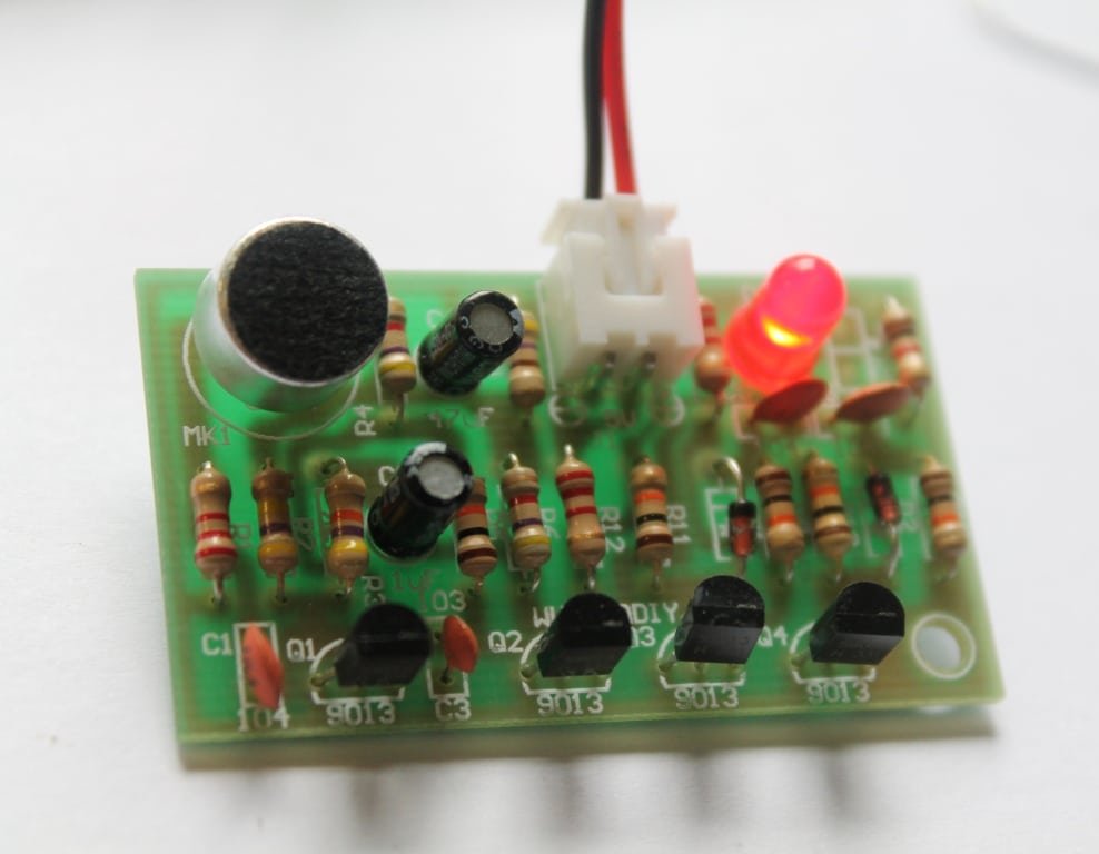
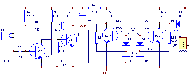
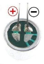
Q1 and Q2 together form an amplifier circuit. MK1 (electret microphone) accepts Clap/Audio signal and that enters to transistor Q1 through the coupling capacitor C1 and enters to Q2 base through collector directly after getting amplified. And it obtains a negative square-wave which used to trigger the bistable circuit from Q2’s collector.
R1 and C1 restrict the frequency response of circuit to 3kHz which is in a high sensitivity range. Q4 is cutoff while Q3 is saturated and D3 is off when the power is on. When MK1(electret microphone) obtains the control signal, a negative square-wave is output after amplification and negative pulse is added to Q3 base through D1 after differentiation processing. The power flips rapidly and D3 is switched on at this time. The power flips again when MK1 obtains the control signal at the second time and the LED D3 goes off. A cable terminal J1 can be added on PCB which used for connecting external control equipment. It can realize the sound control function on other equipment by connecting J1 and relay.
A diode should be connected reversely at the ends of relay when connecting the relay. You can learn about relay from this link.
This circuit works with 6V-9V power supply. The circuit consumes 3mA when the LED is off, and it takes 6mA when the LED is on.

Schematic:
 Documents:
Watch the video:
You can purchase this basic clap switch kit from our store.
We are now selling a fully assembled clap switch that can turn on/off 110-220V AC lights.

🛠️ Dive into our collection of DIY Kits, 🔊 Audio Amplifiers, Digital Scoreboards, FM transmitters, and more!
🎶 Explore endless possibilities at our new store.


what should i do if im going to use that with 220 volts with 220 bulb?
please post the image of the PCB with the foil part
I am in Ghana and i want the required components for a DIY clap switch.Please tell me how to get some in Ghana,maybe a store or something like that.And also send me the pictures of the components on facebook:Emmanuel Botchey,profile picture is astro boy or email me
Please I want to build a light/darkness Detector which I can use on 220v.What parts do I need?