


How to make a batteryless (crystal set) radio

CRYSTAL SET
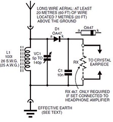
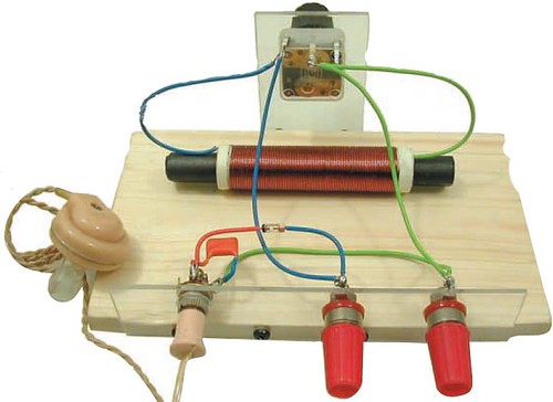
The simplest radio receiver, known as a Crystal Set, consists of nothing more than a coil, tuning capacitor, diode detector, and a pair of earphones. A typical circuit diagram for a Crystal Set Radio is given below where inductor or coil L1 is tuned by variable capacitor VC1 to the transmitter frequency. Diode D1 demodulates the signal, which is fed straight to the earphones. There is no amplification.
* You can use 1N34 Germanium diode in place of OA47
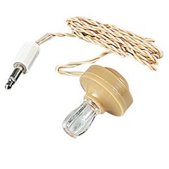
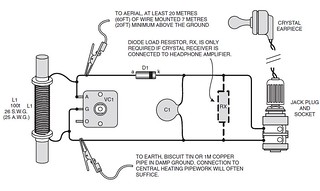
A long (at least 20 metres), high (17 metres or more) aerial and a good earth (a buried biscuit tin or a metre of copper pipe driven into damp ground) are required in order to ensure audible headphone reception. The earphones originally used with these receivers had an impedance of around 4000 ohms and were very sensitive (and heavy and uncomfortable). They are no longer available, but a crystal earpiece, which relies on the piezoelectric effect, will give acceptable results.
Low impedance ”Walkman” type earphones are NOT suitable.
Component details:
Resistor- RX-4.7k, 0.25 W- only required if set is connect to audio amplifier
Capacitors- C1- 10nF disc ceramic VC1- 5p to 140p, polythene dielectric variable capacitor.
Semiconductors: D1: OA47 or 1N34- Germanium Diode
Miscellaneous: L1- Ferrite Rod, 100mm(4 inch)x9mm/10mm dia., with coil.
Crystal earpiece and jack socket to suit; plastic control knob; plastic insulated flexible cable for aerial wire, downlead and earth connection, 30 meters minimum; buried biscuit tin or 1 meter of copper pipe for earth system; 50gm reel of 26SWG enamelled copper wire, for tuning coil; card and glue for coil former; multistrand connecting wire; crocodile clips or terminals for aerial and earth lead connection; solder, etc.
 READ MY EXPERIENCES- HOW EASILY I MADE A BATTERYLESS RADIO
DRAWBACKS
Quite apart from the absence of amplification, two factors seriously limit the performance of crystal receivers. Germanium diodes become increasingly reluctant to conduct as the applied voltage falls below 0.2V, and this makes the receiver insensitive to weak signals. Silicon diodes have a threshold of around 0.6V, and are, therefore, unsuitable for circuits of this kind.
* Silicon diodes like 1N4001 are not suitable
The earphone loading imposes heavy damping on the tuned circuit, hence, reduces its ability to separate signals. With such low selectivity insensitivity can be a blessing, and crystal sets are normally only capable of receiving a single, strong transmission on the long and medium wavebands. They will sometimes receive more than one if a shortwave coil is fitted.
The aerial and diode can be connected to tappings on the tuning coil in order to reduce damping, but the improvement in selectivity is usually at the expense of audio output. When valves cost a week’s wages and had to be powered by large dry batteries and lead/acid accumulators, the construction of simple receivers of this kind could be justified. With high performance transistors now costing only a few pence or cents, crystal sets are now regarded as ‘nostalgic pieces”. Some readers may, however, wish to build one out of curiosity, or for the novelty of having a receiver that does not require a power supply.
CIRCUIT DETAILS
Ferrite loop aerial L1 and polythene dielectric variable capacitor VC1 form the tuned circuit. Point contact germanium diode D1 (1N34 or OA47) demodulates the signal; capacitor C1 bypasses residual r.f. (radio frequency) to earth and also exhibits a reservoir action, enabling the a.f. (audio frequency) output to approach its peak value. The recovered audio signal is fed directly to a crystal earpiece. Signal voltages introduced in the ferrite loop aerial by the radiated magnetic field are much too much to produce an output from the detector, and the component is used here simply as a tuning coil. The ferrite core does, however, reduce the number of turns required for the coil winding, thereby reducing its resistance and increasing its audio quality.
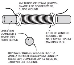
COIL DETAILS
Full construction and winding details for the ferrite tuning/ aerial coil L1 are shown in figure.
The coil is made from 26 SWG(25 AWG) enamelled copper wire, close wound on a cardboard former.
The r.f. bypass capacitor C1 can in practice, be omitted with no noticeable reduction in performance. However, if the set is to be connected to either the headphone amplifier or speaker amplifier decribed next month, the component together with diode, load resistor, RX, must be included.
AMPLIFICATION Audio frequency amplification, after the diode detector will permit the use of low impedance Walkman type earphones or even loud speaker operation. It will do nothing, however, to overcome the diode’s insensitivity to weak signals. For this we must have radio frequency amplification of the signals picked up by the aerial before they reach the detector(The standard circuit for a transistor portable receiver has three stages of radio frequency amplification ahead of the diode).
For amplification, you can use a simple audio amplifier using LM386.
READ MY EXPERIENCES ON MAKING A BATTERYLESS RADIO
WATCH THESE VIDEOS:
🛠️ Dive into our collection of DIY Kits, 🔊 Audio Amplifiers, Digital Scoreboards, FM transmitters, and more!
🎶 Explore endless possibilities at our new store.


Hurrah, that’s what I was searching for, what a data! existing here at
this website, thanks admin of this web site.
cool
thank you sir
thank you sir
sir can you please upload circuit of led receiver
What I was searching for is a small AM radio that I got in a box of cereal in the 50’s. It had a button type earphone. Very small. All I had to do was to hook up 1 alligator clip to a ground, like a water pipe. Tuning was made with a small rod inside a tube. All you had to do was move the rod in or out till you got a station. Anybody remember them? I tell people about this and most never heard of it. Appreciate and feed back.