


Sound generator and Musical toy organ
One of the main objectives of LDR Engineering projects is to make students capable of developing their own logic for making devices. Here is an example that tells how LDR Engineering helps in developing ideas.
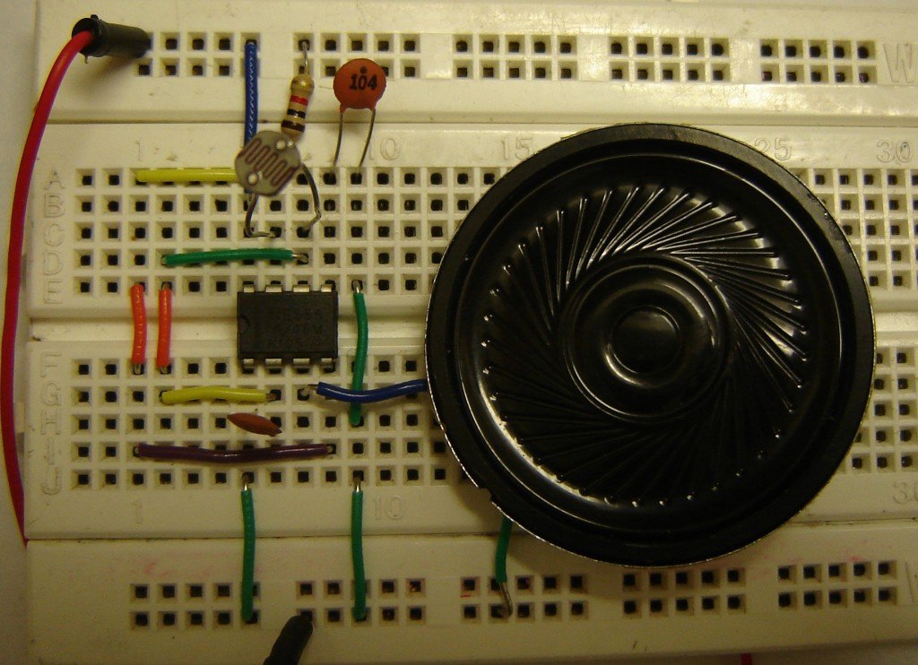
The figure below shows the schematic for making ‘Sound generator using 555 and LDR’. It is based on astable mode of 555 timer. This circuit can be used to understand how resistance plays an important role in the output frequency of NE555 timer. The main idea is to change the resistance of LDR and see the change in output frequency.
CLICK HERE: Astable operation

In the following circuit arrangement, I have excluded VR1-100K and R1-330R resistance. The circuit work without these two components. You can make the circuit seeing the picture given below.

Now, we can present the same project in a bit different way.The figure is given below.

The project given above is a simple musical toy organ and this circuit has been developed on the basis of ‘sound generator using 555’. Therefore, ideas presented in a different way can make different devices.
In the circuit given below, I have used 1K resistor in place of VR1- 10K and used 10K and 15K resistors in place of 1K ‘resistors in the series’ network.
")
")
")
Similar project
You can read about a similar DIY kit at this page: https://www.buildcircuit.com/diy-kit-24-ne555-based-piano-kit/
🛠️ Dive into our collection of DIY Kits, 🔊 Audio Amplifiers, Digital Scoreboards, FM transmitters, and more!
🎶 Explore endless possibilities at our new store.


