About relay module for clap switch- operate 100-240V appliance

connecting a lamp

Description: This is a dependent DIY kit module that has to be used with a clap_switch available at buildcircuit.net. This kit DOES NOT work independently as a clap switch. It is useless without this_clap_switch_kit. So, you need to order that kit also.

You can read about the clap-switch at this link.

clap-switch-diy-kit

The relay module is operated by this clap switch

 Buy now button

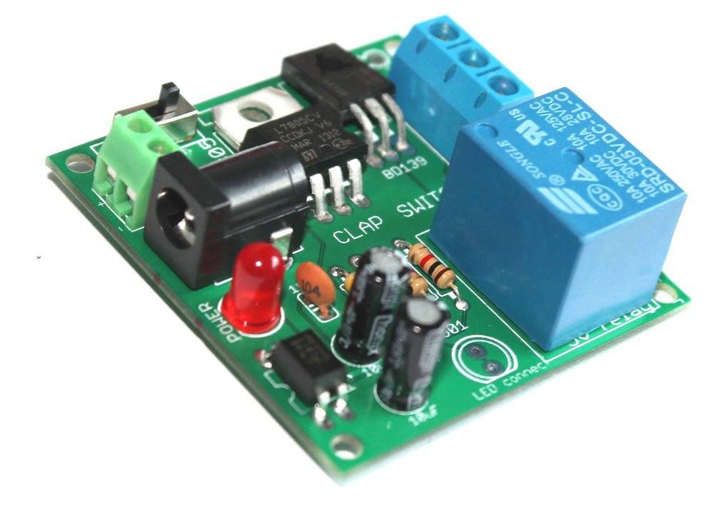
The relay module comes as a pack of parts kit and is easily assembled if you can follow the silkscreen indicators (labels) and have beginning experience with a soldering iron. You will need to read the resistor bands or use a multimeter to determine the resistor sizes. Both the kits operate with 9V batteries.

Step 10- Solder 5V relay and your kit is ready for blog

Features:

  • A DIY kit module that works with this_clap_switch_kit. It is useless without the clap switch.
  • >Operates a 100-240V lamp with clap/loud sound.
  • Supply voltage: 6V-9V. The same power supply can be used for this_clap_switch_kit.
  • There are two supply input points: a DC barrel and a screw terminal. You can use one of the points to power up the kit.
  • Dimension: 48.26mm x 49.53mm.
  • Relay specification: Activation voltage: 5V DC. Controls appliances operating at 10A 250VAC, 10A 125VAC, 10A 30VDC, 10A 28VDC. Suitable for Europe, North America, Australia and New Zealand.

Schematic of relay module:

Click on the image to enlarge it.

schematic relay module for clap switch

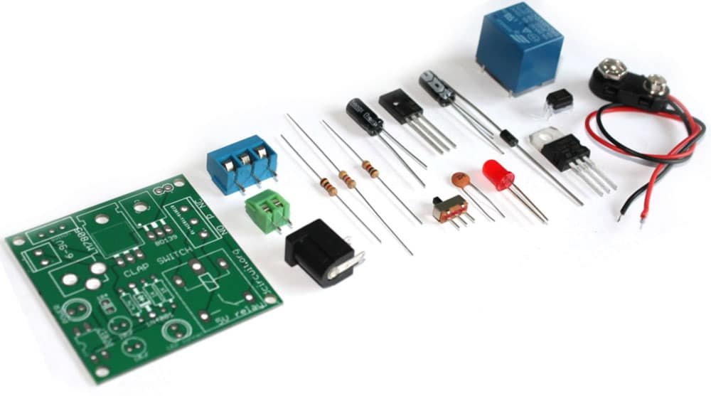
The kit package contains the following components:

  1. 1 x Bare PCB with Silkscreen indicators
  2. 2 x 1K carbon film resistor
  3. 1 x 4.7K carbon film resistor
  4. 1 x 1N4001 diode
  5. 1 x LM7805
  6. 1 x BD139
  7. 1 x 0.1uF (code- 104)
  8. 2 x 10uF capacitor
  9. 1 x PC817 optocoupler
  10. 1 x SPDT switch
  11. 1 x 5V relay
  12. 1 x 3 pin screw terminal
  13. 1 x 2 pin screw terminal
  14. 1 x DC barrel
  15. 1 x 5mm LED
  16. 1 x 9V battery connector

Buy now button

Documents:

Video:

How to connect the relay module to the popular clap switch


connecting a lamp

This article strictly focuses on how to connect the relay-module to the popular clap-switch. If you have come to this page from a search engine, we recommend you to visit the following pages:

1. About Relay module for the popular clap_switch (Get description of this kit)

2. How to connect clap-switch to the relay module

3. How to use the relay-module and the clap-switch to operate electrical appliances

Please follow the shown steps:

Step 1: Connect the cathode point of clap-switch to the cathode of relay-module.

Step 1- connect the cathode pin of clap switch kit to the anode pin of relay module

Step 2: Connect the anode point to anode point.

Step 2- Connect the anode pin of clap switch kit to the anode pin of relay module

Step 3: Connect the JST connector of clap-switch module to the relay-module. The clap-switch module gets power from the relay-module.

Step 3- Connect the black(negative) wire of clap switch to -ve pin on the board and do the same for the red (positive) wire also

Step 4: Connect a 9V battery to power up the kits. The clap-switch module gets power from the relay-module.

The connection between the kits is ready

Step 5: This is how you connect the lamp to the combination of kits. 

connecting a lamp


This kit is available at our online store www.buildcircuit.net.

Step 10- Solder 5V relay and your kit is ready

Buy now button


Video:

Recommended documents:

Assembly tutorial- Relay module DIY kit for popular clap switch

connecting a lamp

In this article, we have described how you can assemble your relay module for the popular clap-switch. If you have come to this page from a search engine, we recommend you to visit the following pages:

Related articles:

1. About Relay module for the popular clap_switch (Get description of this kit)

2. How to connect clap-switch to the relay module

3. How to use the relay-module and the clap-switch to operate electrical appliances

You can see the following steps to make your relay module for the popular clap-switch.

PCB

Step 1: Solder 2pcs of 1K resistor and 4.7K resistor

Step 1- Solder 4.7K and 1K resistors

Step 2: Solder 1N4001 diode

Step 2- Solder 1N4001 diode

Step 3: Solder LM7805 voltage regulator and BD139 transistor

Step 3- Solder LM7805 and BD139

Step 4: Solder 0.1uF capacitor

Step 4- Solder 0.1uF capacitor

Step 5: Solder PC817 optocoupler

Step 5- Solder PC817 optocoupler

Step 6: Solder SPDT switch and 2 pin screw terminal

Step 6- solder SPDT switch and 2 pin screw terminal

Step 7: Solder 5mm LED. This works as power indicator

Step 7- Solder 5mm LED for power indicator

Step 8: Solder DC barrel for connecting power supply.

Step 8- Solder DC barrel and 2pcs 10uF capacitors

Step 9: Solder 3 pin screw terminal

Step 9- Solder 3 pin screw terminal

Step 10: Solder 5V relay

Step 10- Solder 5V relay and your kit is ready

Step 11: Connect the cathode point of clap switch module to the cathode point of relay module

Step 1- connect the cathode pin of clap switch kit to the anode pin of relay module

Step 12: Connect anode point of clap switch module to the anode point of relay module

Step 2- Connect the anode pin of clap switch kit to the anode pin of relay module

Step 13: Connect the JST connector of relay module to the + and – point on the clap switch module. The clap switch module gets power from the relay module.

Step 3- Connect the black(negative) wire of clap switch to -ve pin on the board and do the same for the red (positive) wire also 

Step 14: Connect a 6-9V battery to the kit and connect electrical lamp.

The connection between the kits is ready

NOTE: We are selling a slightly different PCB, this will make your job easier. This is better than the previous one. Available in BLUE color. See the image below to know how you can connect the relay module to the clap switch

CLICK HERE to see all the steps- How to connect a lamp to the relay module

Step 15: The following image shows how you can connect a lamp to the relay module

connecting a lamp

Buy now button

Documents:

Video:

How to connect a lamp to DIY relay module for the popular clap switch

The connection between the kits is ready

If you have come to this page from a search engine, we recommend you to visit the following pages:

1. About Relay module for the popular clap_switch (Get description of this kit)

2. How to connect clap-switch to the relay module

3. How to use the relay-module and the clap-switch to operate electrical appliances

In this article, we are going to describe how you can use the “clap_switch module+relay_module” to light up 100-240V appliances. When we say 100-240V appliance used with a clap switch, it is usually a bulb/lamp/CFL(Compact Fluorescent Lamp) tube. This article is for absolute beginners, so, we will try to explain all the small details. (more…)

Search for products

Back to Top
Product has been added to your cart