2 CHANNEL RELAY BOARD
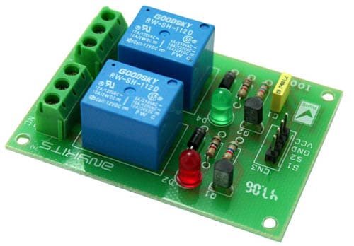
This project is a 2 Channel Relay Board.
DESCRIPTION
2 channel Relay driver project can be controlled by feeding 2-12V trigger voltage, Very useful project for application like Micro-Controller based projects, Remote controller, Lamp on Off, and any circuits which required isolated high current and high voltage switching by applying any TTL or CMOS level voltage. Two LED works as operation indicator while in , 3 pins screw terminals to connect load and provides both normally open and normally closed switching.
- Input: 12 VDC @ 84 mA
- Output: Two SPDT relay
- Relay specification: 5 A @ 230 VAC
- Trigger level : 2 to 12 VDC
- Header connector for connecting power and trigger voltage
- LED on each channel indicates relay status
- Power Battery Terminal (PBT) for easy relay output connection
- Four mounting holes of 3.2 mm each
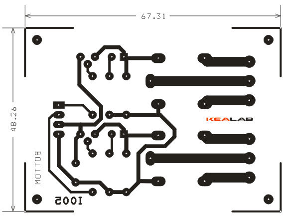
- PCB dimensions 49 mm x 68 mm
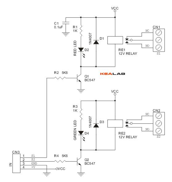
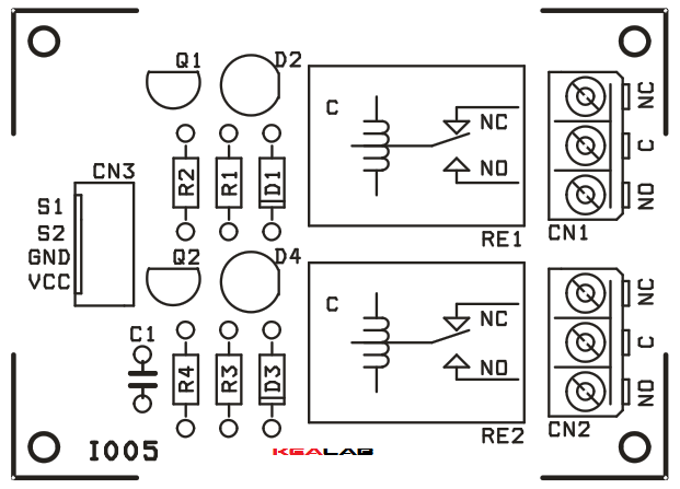
SCHEMATIC
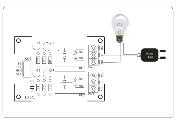
CONNECTION
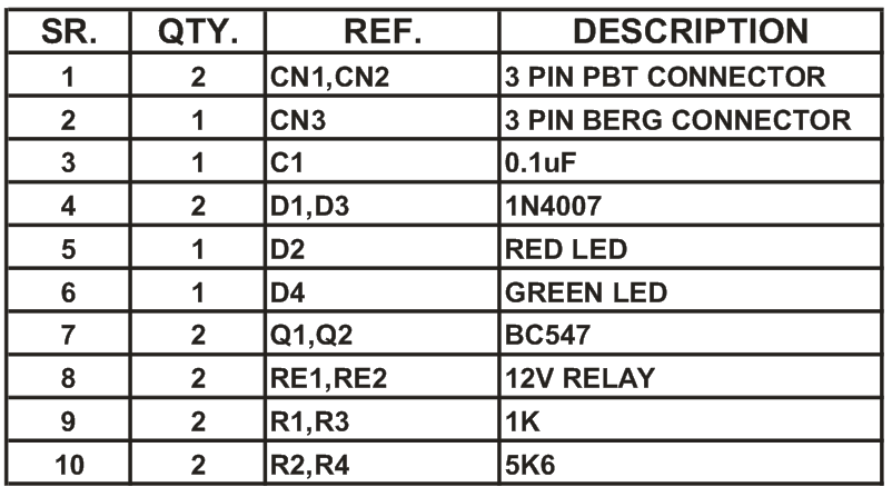
PARTS LIST
PCB
DOWNLOADS
🛠️ Dive into our collection of DIY Kits, 🔊 Audio Amplifiers, Digital Scoreboards, FM transmitters, and more!
🎶 Explore endless possibilities at our new store.