Cosmarino- A DIY kit for Android-Arduino communication

Cosmarino

“Cosmarino is a kit for experimenting Android-Arduino communication via Bluetooth.”

Features: 

  • Control RGB LED with Android phone
  • Display photoresistor sensor data on a graph on Android phone
  • Transmit LM35DZ temperature sensor data on Android phone
  • Control 5V relay with Android phone
  • Control 5V relay and LED with any infrared remote control

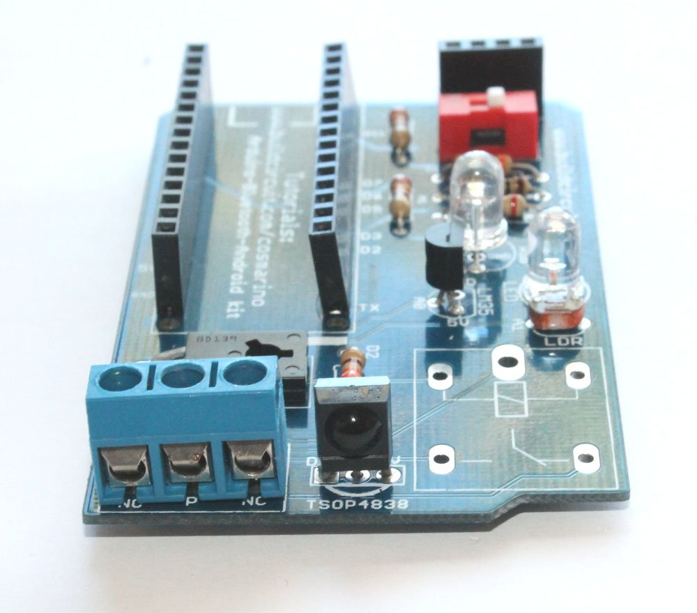
This is Cosmarino- A simple DIY kit for facilitating communication between Arduino Nano and Android via Bluetooth communication medium. The kit also has a TSOP4838 infrared sensor which offers you the possibility of controlling the kit with a normal infrared remote control.

The kit has been designed to support particularly Amarino toolkit Android application, but we have tested the kit with many other applications made for Arduino-Android communication via Bluetooth and all have worked properly.

The kit package includes:

  1. Cosmarino kit- Available in fully assembled and DIY versions
  2. Bluetooth module
  3. Amarino Nano– Chinese version with CH340G chip
  4. Infrared remote control

Cosmarino has the following features:

  • Android app controlled: The Cosmarino kit can be controlled with several Android applications made for controlling Arduino or communicating with Arduino via Bluetooth. We have used Amarino toolkit and many other Android applications for testing different features of the kit.
  • Bluetooth support: The control signals from Android phone are sent to Arduino Nano via Bluetooth. There is a Bluetooth module connected to the circuit board that facilitates communication between Android and Arduino.
  • TSOP4838 infrared sensor: There is a TSOP4838 infrared sensor on the circuit board which allows you to control Cosmarino with any kind of TV/DVD remote control. However, the kit package includes an Infrared remote control also.
  • Fully programmable: The kit is fully programmable because it has Arduino Nano.

Experiments:

You can do several experiments with Cosmarino. Some of the interesting experiments have been listed below.

1. RGB LED control: You can control the common cathode RGB LED with your Android smart phone.

multicolor lamp

2. Relay control- Relay on the kit can be controlled with the phone or any remote control.

3. LDR/photoresistor sensor data- Cosmarino can transmit LDR sensor data to your phone. You can receive LDR sensor data and control the 5mm LED at the same time.

This feature is available with Amarino toolkit application only.

sensor graph

5. LM35 temperature sensor data- The kit transmits LM35 temperature sensor data to your phone. You can receive the sensor data and control the 5mm LED at the same time.

This feature is available with Amarino toolkit application only.

temperature sensor

 Schematic: (Click on the schematic to enlarge)

cosmarino

As you can see on the schematic the components have been connected to the Arduino Nano in the following way:

1. OUTPUT- RGB LED: R= D3, Blue= D5 and Green= D6. All these digital pins have Pulse Width Modulation function.

2. OUTPUT- 5mm LED connected to Digital pin D11

3. OUTPUT- 5V relay connected to Digital pin D2

4. INPUT- LDR/Photoresistor connected to Analog pin A1

5. INPUT- LM35 temperature sensor connected to Analog pin A0

6. INPUT- TSOP4838 infrared sensor connected to Digital pin D7

Related documents:

Where can you buy ?

buildcircuit

Cosmarino Assembly Tutorial

If you have come to this page from a search engine, please check this page first, you will eventually come to this page again.

About Cosmarino

The assembly process of the Cosmarino kit is very straight forward. You just need to follow the silkscreen labels to get the idea of assembly. A basic knowledge in soldering is enough for assembling the kit.

To be quick, you can see all the assembly images on Flickr. 

Step 1: Solder all the 220 ohm resistors

Step 1- Solder 220 Ohm resistors

Step 2: Solder 330 Ohm and 10K ohm resistors

Step 2- SOlder 330 Ohm and 10K Ohm resistors

Step 3: Solder 1N4001 diode.

Step 3- Solder 1N4001 Diode

Step 4: Solder LDR/ photoresistor.
Step 4- Solder LDR

Step 5: Solder BD139 NPN transistor
Step 5- Solder BD139 NPN transistor

Step 6: Solder LM35DZ temperature sensor
Step 6- Solder LM35 temperature sensor
Step 6.1- LM35 temperature sensor

Step 7: Solder TSOP4838 infrared sensor
Step 7- Solder TSOP4838 infrared sensor

Step 8: Solder 1P DIP switch
Step 8- Solder 1P DIP switch

Step 9: Solder 5mm white LED
Step 9- Solder 5mm White LED

Step 10: Solder RGB LED
Step 10- Solder common cathode RGB LED
Step 10.1- RGB Common cathode LED

Step 11: Solder 2pcs 15 pin female header
Step 11- Solder 4 pin and 15 pin female headers

Step 12: Solder 3 pin screw terminal
Step 12- Solder 3 pin screw terminal
Step 12.1- 3 pin screw terminal

Step 13: Solder 5V relay
Step 13- Solder 5V relay

Step 14: Stack Bluetooth module and Arduino Nano
Step 14- Stack Bluetooth module and Arduino Nano

The kit is ready to use
Step 15- Use Mini USB cable to program Arduino Nano - Copy


Cosmarino Experiments


Related documents:

Where can you buy ?

buildcircuit   ebay   etsy

How to program Amarino lamp

Recommended app

To know about Amarino lamp, visit this page. 

Amarino lamp is fully programmable. The kit package consists of FTDI basic breakout board, you can use it to program the lamp. The lamp is based on Arduino.

Connect the FTDI basic breakout board to the lamp, open the Arduino programming interface and upload your sketch.

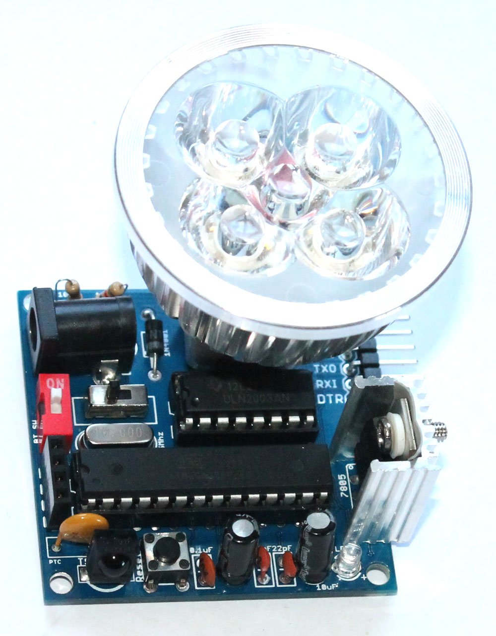
REMEMBER: Turn off the red colored 1P DIP switch 1-position-2p-side-style-dip-switch-redwhile uploading sketch(if the Bluetooth module has been stacked over the 4 pin female header)

programming

Documents: 

  1. About Amarino Lamp
  2. Assembly Tutorial
  3. Amarino Lamp- Light sensor
  4. Lamp test with different phone sensors
  5. How to program Amarino lamp

Where can you buy ?

buildcircuit    etsy

Cosmarino Experiments

If you have come to this page from a search engine, please visit this page first, you will eventually come back to this page again.

About Cosmarino 

Cosmarino is a versatile kit that facilitates communication between Android and Arduino in a simple way.

We can do several experiments with this kit. In this tutorial we have shown experiments related to Amarino only. However, you can test the kit with several other Android app available at Google Play.

Before you start the experiments, please know how the components are connected to the Arduino Nano.

1. OUTPUT- RGB LED: R= D3, Blue= D5 and Green= D6. All these digital pins have Pulse Width Modulation fuctionality.

2. OUTPUT- 5mm LED: Digital pin D11

3. OUTPUT- 5V relay= Digital pin D2

4. INPUT- LDR/Photoresistor= Analog pin A1

5. INPUT- LM35 temperature sensor: Analog pin A0

6. INPUT- TSOP4838 infrared sensor= Digital pin D7

Steps for Amarino experiments: 

Amarino_logo-W490

For all the experiments, you have the following things in common:

Step 1: Amarino Toolkit MAIN application: This is the main Amarino toolkit application to be installed on your Android phone. There are other applications which work only after installing the main application. If the link does not work, download the application from here.

amarino main app

Amarino Nano (1)

Step 2: Amarino Library for Arduino: Download it and move it to the Libraries folder. You can check here if the Amarino team has upgraded the library. It’s always good to use the updated version .

If the given link does not work, you can download the library from this link. 

meet android

Step 3: Connect the Bluetooth module to the circuit board. Please note how the Bluetooth module has been stacked over the 4 pin female header. After you stack it on the circuit board, you will see a red LED blinks on the Bluetooth module.

bluetooth module  Bluetooth module

Step 14- Stack Bluetooth module and Arduino NanoNote how the Bluetooth module has been stacked over the board.

Then, activate the Bluetooth function of your phone.

Amarino Nano (2)

Step 5: After you see an LED blinking on the Bluetooth module, open the Amarino Main application, you see the following interface:

Amarino Nano (1)

On the Amarino main application interface, touch Add BT Device. That will display the Bluetooth module close to your Android phone.

Amarino Interface

Select the linvor Bluetooth module. Remember to note down the MAC ID also. In this example, the MAC ID is 20:13:05:09:15:39. It is unique for all the modules. You will need this MAC ID in the next step. Note that the MAC ID is unique for all modules. It is never same for any two Bluetooth modules.

Pressing the “Connect” button display a text box(for the first time), where you need to enter the pairing code, which is 1234. This connects the application to the chosen adapter. You can connect only one adapter at one time.

Pairing code: 1234

Once the adapter is paired up, you don’t need to pair it again. 

Now we can move to the experiments below:

 Experiment 1- RGB LED Control: 

RGB LED is connected to digital pins 3(RED), 5(GREEN) and 6(BLUE).

  • Download the RGB LED control application and install it on your phone.
  • Download the Arduino source code and upload it to your Arduino Nano. NOTE: You need to switch off the 1P DIP switch while uploading the sketch. After uploading switch it on again.
  • Set Bluetooth MAC ID. It is different for all Bluetooth modules. For example, my Bluetooth module has MAC ID: 98:D3:31:70:3A:98, so, I used that. No two Bluetooth modules can have the same MAC ID. You will have a different MAC ID for your module. Enter the MAC ID that you had noted down in the previous step.

RGB control application

  • As soon as you open the application, the app will connect to the Bluetooth module and you can simply control your RGB LED. As you move the slider, the color on the RGB LED changes. Remember to switch on the 1P DIP switch, otherwise, it won’t work. 

The multicolor lamp application

RGB LED control using “Arduino Bluetooth RGB LEDs” android App:

Cosmarino app

There are several Android applications that can control Amarino Nano kit. Here’s one application that we have tested:

You can then simply connect Bluetooth of your phone to the external Bluetooth module and control the Amarino Nano kit.

Experiment 2: Sensor Graph display

The photoresistor/LDR is connected to A1 and the 5mm white LED is connected to D11.

  • Download the sensor graph application and install it on your phone.
  • Download the Arduino source code and upload it to your Arduino Nano. NOTE: You need to switch off the 1P DIP switch while uploading the sketch. After uploading switch it on again.
  • Set Bluetooth MAC ID. It is different for all Bluetooth modules. For example, my Bluetooth module has MAC ID: 98:D3:31:70:3A:98, so, I used that. You will have a different MAC ID for your module.

Sensor Graph

  • Open the application and see the sensor data on your phone. You may also control the 5mm LED simultaneously. Remember to switch on the 1P DIP switch, otherwise, it won’t work. 

sensor graph (2)

Experiment 3: LM35 temperature sensor data display

  • Download the LM35 temperature senor display application and install it on your phone.
  • Download the Arduino source code and upload it to your Arduino Nano. NOTE: You need to switch off the 1P DIP switch while uploading the sketch. After uploading switch it on again.
  • Set Bluetooth MAC ID. It is different for all Bluetooth modules. For example, my Bluetooth module has MAC ID: 98:D3:31:70:3A:98, so, I used that. You will have a different MAC ID for your module.

temperature sensor log in

  • Open the application and see the sensor data on your phone. You may also control the 5mm LED simultaneously. Remember to switch on the 1P DIP switch, otherwise, it won’t work. 

LED control app interface

Relay control

There is a 5V relay on the Cosmarino kit. You can control the relay using your phone application or a normal infrared remote control.

Control the relay using general Android application and Infrared remote control

There are hundreds of applications on Google Play that have been made for Arduino and Android application. You can pick up any of those apps and control the kit.

In this example, we have picked up this application which transmits text ‘h’ every time the green button is pressed. We have programmed it in such a way that the relay is switched on if the Arduino gets an ‘h’.

TIP: If you want to know what text a random Android app sends to Arduino, you can check out this tutorial. The tutorial shows you what Arduino receives from the phone and what Arduino sends to the phone. See this video also.

The kit is fully programmable. Please remember to switch off the red DIP Bluetooth switch while programming, otherwise, the Arduino Nano cannot be programmed. You should switch it back again after the kit has been programmed.

Step 1: Install this Android application from Google Play.

external app

Step 2: Upload any of these sketches:

If you intend to control the relay with infrared remote control, then, you need to download the library and copy it to the libraries folder of Arduino.

Download Infrared sensor library from the original link 

Step 3: Open the Android application and search for the Bluetooth module stacked on the circuit board. Pair up the module with your Android application(to be done only once). Pairing code= 1234. You need to pair up with the module only once.

Step 4: Switch on/off the relay with the application. You can simultaneously control the lamp with your infrared remote control also if you have uploaded this sketch.

Related documents:

Where can you buy ?

buildcircuit   ebay   etsy

Search for products

Back to Top
Product has been added to your cart