


Assembly tutorial for ESP8266 test board
This is one of the simplest ESP8266 test board for beginners. We have sold several copies of this board on Ebay and on our website. This tutorial should help you assemble your ESP8266 test board. Basic soldering skill is enough to assemble this board.
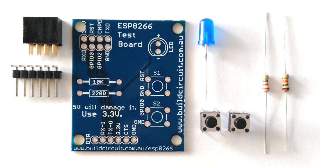
You will receive these components:

The schematic of this kit is given below:

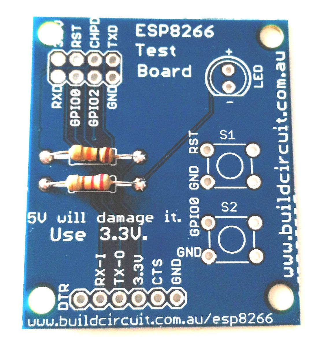
The PCB has silkscreen labels which clearly shows where to fix the right components.

Step 1: Solder the resistors 10K and 220 Ohm. There are only two resistors. 220 Ohm connects to LED and 10K connects to reset switch.
Step 2: Solder the 6 pin male header. The male header is used to connect FTDI basic breakout board.

Step 3: Solder 2pcs of tactile switches

Step 4: Solder 5mm LED. The flat part of the LED is cathode (-) and the other side is anode.
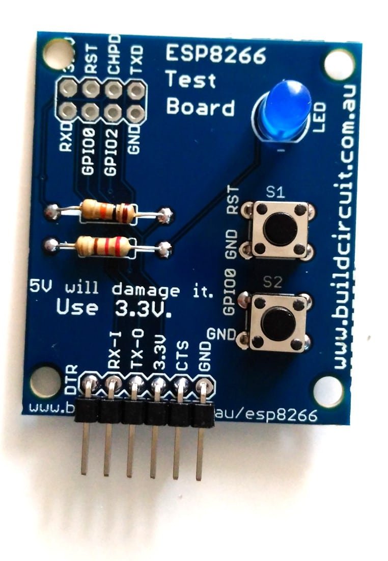
Step 5: Solder the 8 pin header

Your ESP8266 test board is now ready. You can simply stack the ESP8266 module on to the 8 pin female header and connect an FTDI basic breakout board to test the module.


Check out the video:

🛠️ Dive into our collection of DIY Kits, 🔊 Audio Amplifiers, Digital Scoreboards, FM transmitters, and more!
🎶 Explore endless possibilities at our new store.

