


Dark Sensor using 741

A varying input voltage (pin 2) is compared with a fixed reference voltage (pin 3). If the input voltage is higher than the reference voltage, then the output is negative. If the input voltage is lower than the reference, then the output is positive.
Suppose that, resistance of LDR is 15K in dark and 1K in light. If we fix the variable resistor at 40K, then, according to the voltage divider rule:
Voltage at pin 3(Reference Voltage):
Vref =[120K/(120K+40K)]*6V = 4.5V
In dark, input voltage at pin 2,
Vin = [15K/(15K+15K)]*6V = 3V
Here, from the calculation we can find that Vin < Vref
So, the output is positive, this switches on the LED.
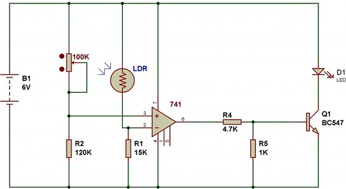
In light, the resistance of LDR is supposed to be 1K, in that case, the reference voltage at pin 3 = 4.5V
In light, input voltage at pin 3,
Vin = [15K/(1K+15K)]*6V = 5.625V
Here, from the calculation we can find that Vin > Vref
So, the output is negative and that switches off the LED.
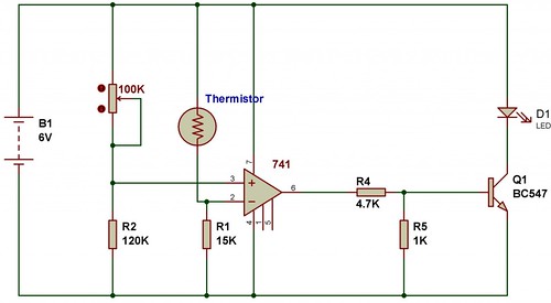
Heat Sensor using 741
To make a heat sensor we just have to replace an LDR with an NTC type thermistor.The calculation done for the previous circuit can be used to understand the operation of automatic heat sensor.
🛠️ Dive into our collection of DIY Kits, 🔊 Audio Amplifiers, Digital Scoreboards, FM transmitters, and more!
🎶 Explore endless possibilities at our new store.


is it 100k rehostate ..??
I built a circuit just like this but I have the LDR and the resistor in the switched mine detects dark and turns on a light
Put a resistor(330Ω…1kΩ) in series with that LED. Otherwise it will blow, and the transistor too.
” If the input voltage is higher than the reference voltage, then the output is negative. If the input voltage is lower than the reference, then the output is positive. ”
How much is the difference’s value that can be read as the difference between the voltage reference and input voltages, so the output voltage can result in positive or negative?
Thank you!