


How to use a relay

A relay is an electrically operated switch. Current flowing through the coil of the relay creates a magnetic field which attracts a lever and changes the switch contacts. The coil current can be on or off so relays have two switch positions and they are double throw (changeover) switches.
The relay’s switch connections are usually labeled COM(POLE), NC and NO:
COM/POLE= Common, NC and NO always connect to this, it is the moving part of the switch.
NC = Normally Closed, COM/POLE is connected to this when the relay coil is not magnetized.
NO = Normally Open, COM/POLE is connected to this when the relay coil is MAGNETIZED and vice versa.
A relay shown in the picture is an electromagnetic or mechanical relay.


Fig. Relay and its symbol
There are 5 Pins in a relay. Two pins A and B are two ends of a coil that are kept inside the relay. The coil is wound on a small rod that gets magnetized whenever current passes through it.
COM/POLE is always connected to NC(Normally connected) pin. As current is passed through the coil A, B, the pole gets connected to NO(Normally Open) pin of the relay.
Here is an example,
First of all try the following circuit.
This is a dark sensor circuit.
![]()
Fig. Dark sensor using two transistors
Output of this circuit: When you block light falling on LDR, the circuit switches on the LED- D1.
Now, replace LED-D1 and R2- 330R with a relay and diode.
Reconfigure the circuit as shown in the figure below:
Note: In R3, you can keep any resistor from 330R to 4.7K, this resistor is for sensitivity of the dark sensor.
The following circuit also works as a dark sensor. When you block light falling on LDR, the relay gets activated and Pole of relay gets connected to NO pin that eventually gives power to LED- D1.


Fig. Dark sensor using two transistors and a relay.
Light sensor using relay and transistors
In this case, the configuration of relay has been changed. Here, NO (Normally open) terminal has been left open. In normal case, the D1-LED remains ON. When light falling on LDR is interrupted, pole of relay gets connected to NO terminal. Hence, NC (Normally connected) terminal does not get power and that switches the D1- LED off.

Fig. Light sensor using two transistors and a relay.
Connect to COM(pole) and NO if you want the switched circuit to be on when the relay coil is on.
Connect to COM(pole) and NC if you want the switched circuit to be on when the relay coil is off.
WORKING WITH 220V
WARNING: IF YOU ARE A NOVICE DO NOT PLAY WITH 220V AC. CALL AN EXPERIENCED PERSON FOR ASSISTANCE.

Fig. Dark sensor circuit for 220V powered lights.
A relay can be used to turn on lights working on 220V, AC. The AC powered light has to be connected to relay as shown in the picture above.

Fig. Connecting wires on relay
The following video shows a soldered/finished prototype.
PROTECTION DIODE FOR RELAY

Fig. Protection diode in the circuit
Transistors and ICs must be protected from the brief high voltage produced when a relay coil is switched off. The diagram shows how a signal diode (eg 1N4148 or 1N4001 or 1N4007) is connected ‘backwards’ across the relay coil to provide this protection.
Current flowing through a relay coil creates a magnetic field which collapses suddenly when the current is switched off. The sudden collapse of the magnetic field induces a brief high voltage across the relay coil which is very likely to damage transistors and ICs. The protection diode allows the induced voltage to drive a brief current through the coil (and diode) so the magnetic field dies away quickly rather than instantly. This prevents the induced voltage becoming high enough to cause damage to transistors and ICs.
GENERAL SPECIFICATION OF A RELAY

06VDC- means that the voltage across the relay coil has to be 6V-DC.
50/60Hz- The relay can work under 50/60Hz AC.
7A, 240VAC- The maximum AC current and AC voltage specification that can be passed through NC, NO and pole pins/terminals of relay.
One more example (update 19.3.2014)
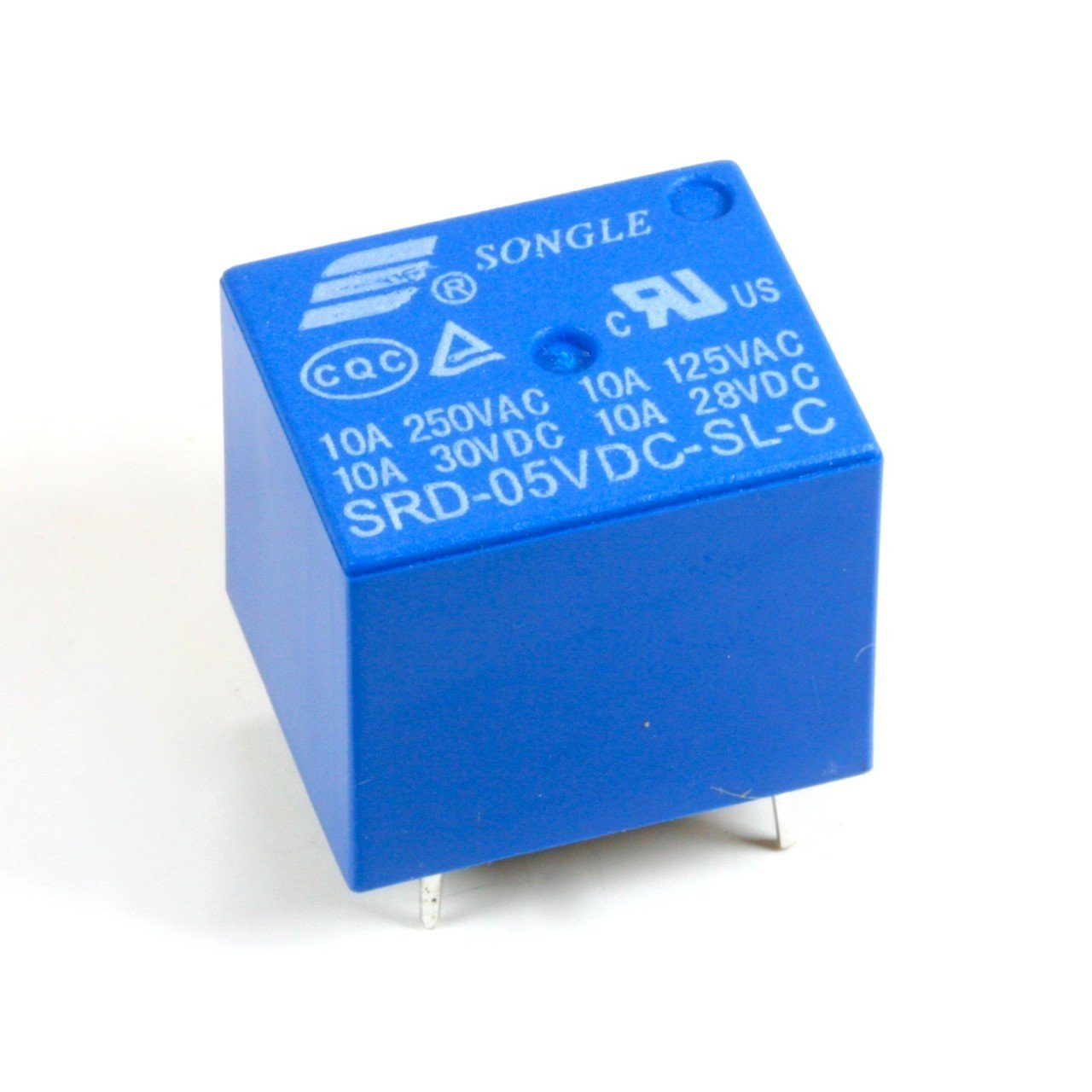
05VDC- It means that you need 5V to activate the relay. In other words, it means that the voltage across the relay coil has to be 5V-DC.
10A 250VAC 10A 125VAC – The maximum AC current and AC voltage specification that can be passed through NC, NO and pole pins/terminals of relay. Some countries have 220V AC power standard, so, it works in those countries also.
10A 30VDC 10A 28VDC- The maximum DC current and DC voltage specification that can be passed through NC, NO and pole pins/terminals of relay.
Tips:
– If you are using a 5-6V relay, use a 6V power supply.
– If you are using a 9V relay, use a 12V power supply.
🛠️ Dive into our collection of DIY Kits, 🔊 Audio Amplifiers, Digital Scoreboards, FM transmitters, and more!
🎶 Explore endless possibilities at our new store.
