DIY KIT 59- How to assemble DIY digital clock kit ?
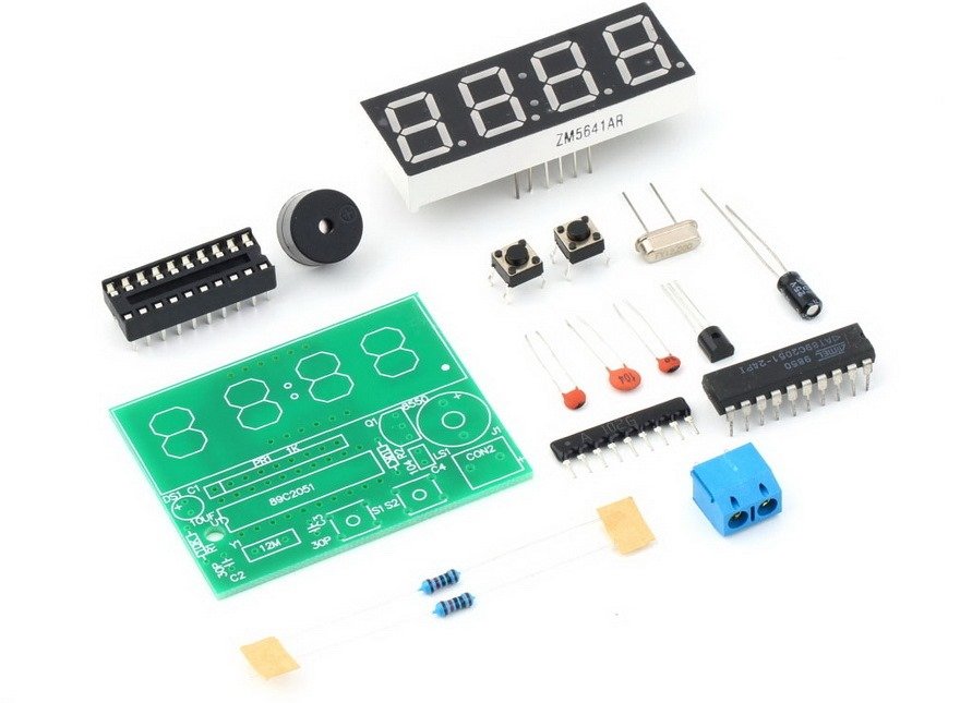
If you have come to this page directly from a search engine, visit this page first to know about this DIY digital clock kit.
This assembly tutorial explains how to assemble the DIY digital clock kit.
You will get the following components in the kit package:
 You will need basic soldering skills to assemble the kit. If you follow the PCB silkscreen labels, you can easily solder the kit.
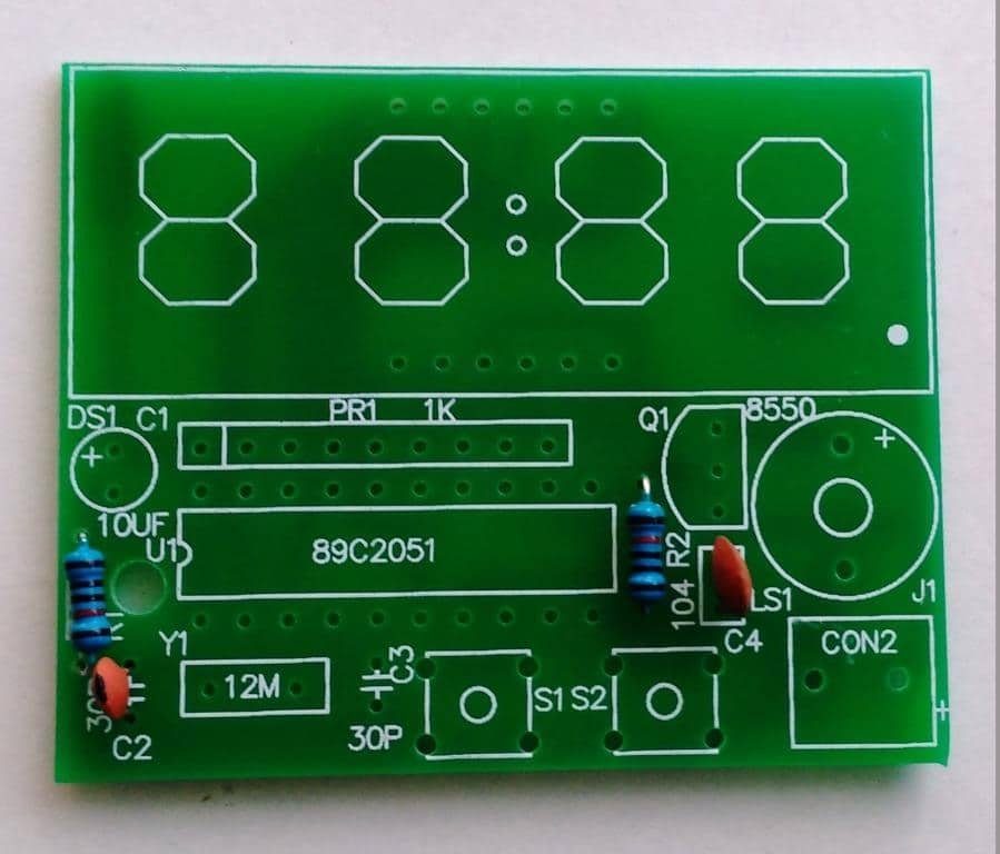
Step 1: Solder two Resistors and capacitors 30pF(code-30) and 0.1uF (code-104).
Step 2: Solder the other 30pF capacitor also.
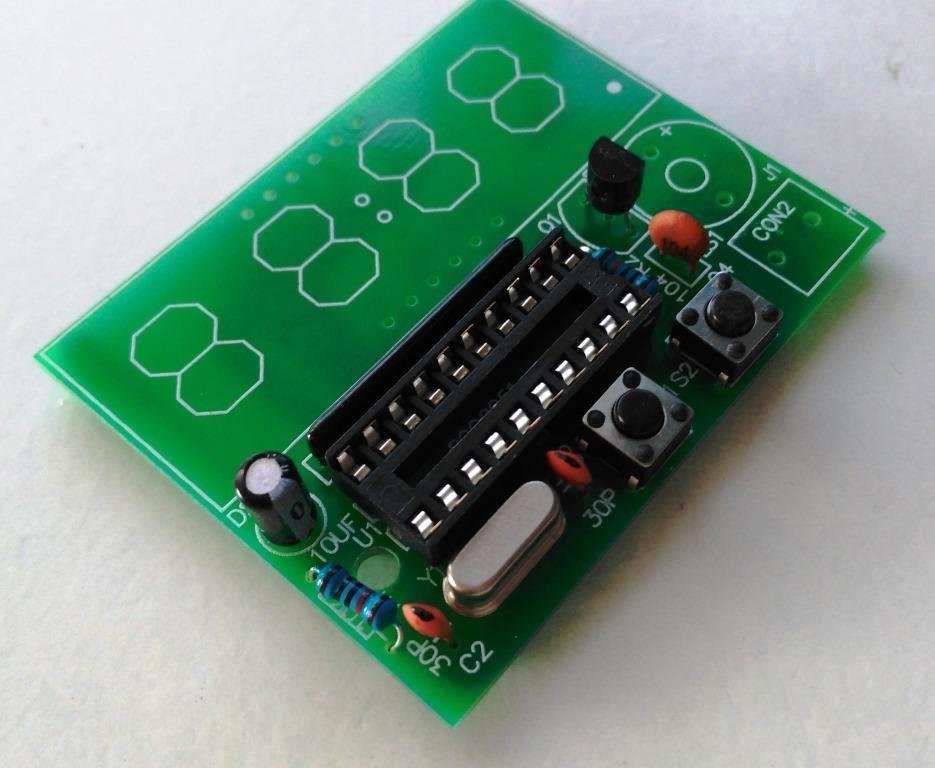
Step 3: Solder the 12Mhz crystal oscillator.
Step 4: Solder 2pcs tactile switches
Step 5: Solder SS8550 transistor.
Step 6: Solder IC socket and SIP-9 1k resistor. The resistor is used to control current in the seven segment display
Step 7: Solder 10uF capacitor. Be careful with the capacitor polarity. Insert positive pin of the capacitor in the hole marked +
Step 8: Solder 5mm screw terminal. You will use this terminal to connect battery.
Step 9: Solder the buzzer. Note the polarity of the buzzer.
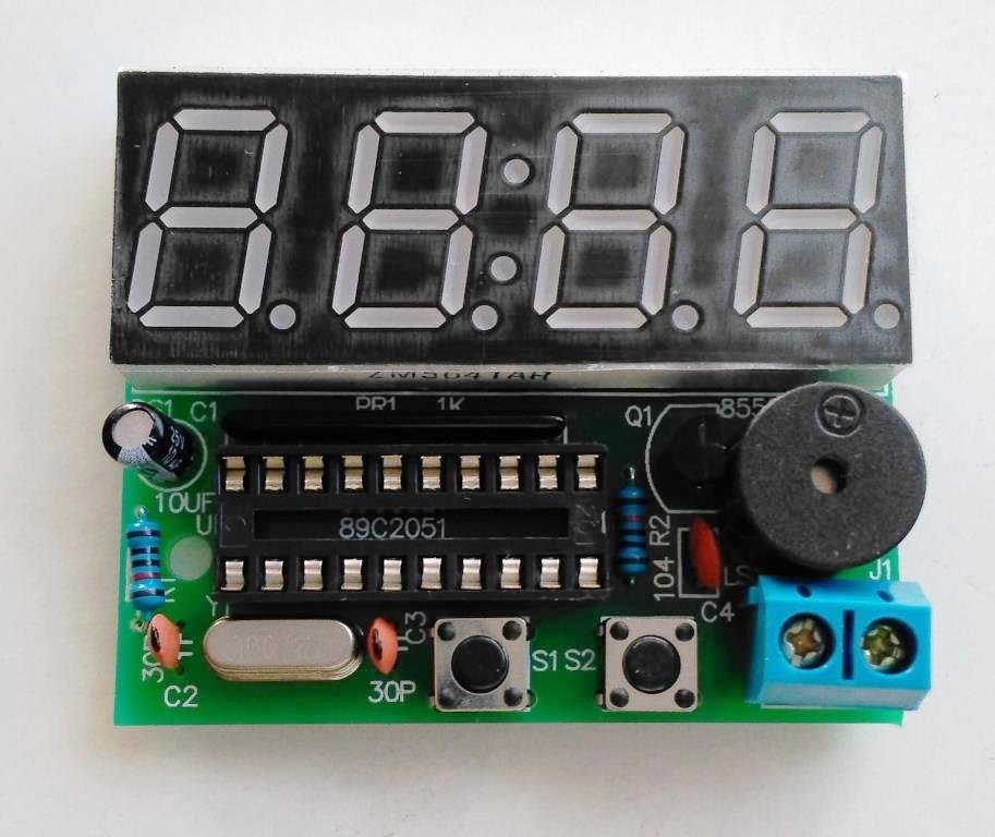
Step 10: Solder 4 digit seven segment display
Step 11: Insert the microcontroller chip in the IC socket
Step 12: Connect a 9V battery connector to the screw terminal. You can now use the digital clock.
Digital clock DIY kit is available at www.buildcircuits.com.


