MICROCONTROLLER BASED RUNNING LIGHT CONTROLLER
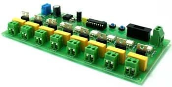
This project is a lights effects board using common bulbs.
DESCRIPTION
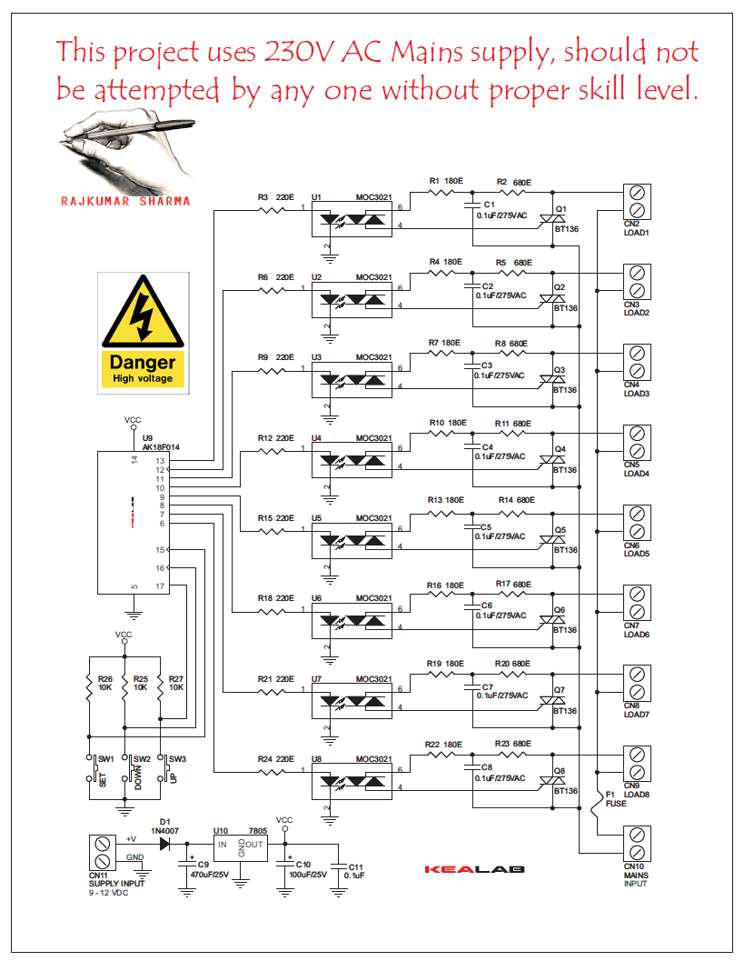
This project provides some lighting effect by the blinking pattern of the bulbs connected at its output. Up to 8 Bulbs can be connected in between connector CN2 to CN9 and AC power to control them should be connected at Connector CN10. DC Power should be applied at Connector CN11 in accordance with the polarity marked on this connector. Care should be taken while using this it as it contains Main Power on the board.
We can change the Blink pattern by the press of the SET switch and change the blinking speed by the press of the UP and DOWN keys on the PCB. Fuse F1 will protect the Kit from any possible short circuit and excess current flowing through it.
FEATURES:
- Microcontroller based design for greater flexibility and ease of control
- Triac based switching of loads connected to the circuit
- Industry standard isolation with the help of Opto enabled Triac Control
- Fuse protection for AC output
- SUPPLY 9-12V DC & 230V AC
- LOAD-100W max on each output
- Simple and easy to use 3 tactile switch enabled control of the project
- PBT type connector for connecting supply (AC/DC) and TRIAC output on the PCB
- Onboard regulator for regulated supply to the project
- Diode protection for reverse polarity connection of DC supply to the PCB
- Four mounting holes of 3.2 mm each
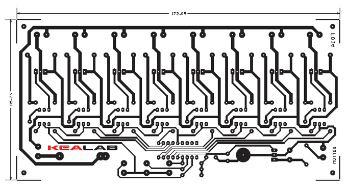
- PCB dimensions 86 mm x 173 mm
SCHEMATIC
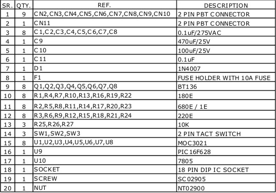
PARTS LIST
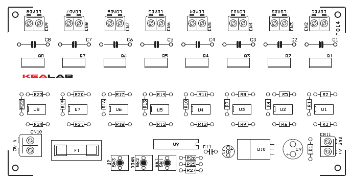
PCB
🛠️ Dive into our collection of DIY Kits, 🔊 Audio Amplifiers, Digital Scoreboards, FM transmitters, and more!
🎶 Explore endless possibilities at our new store.