


Mode of NE555- Astable
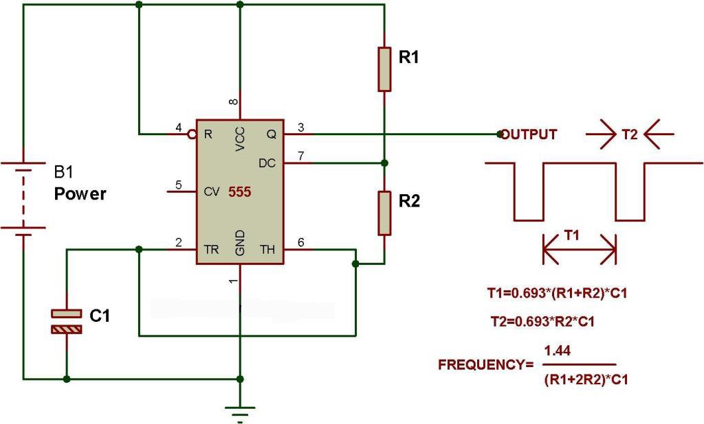
This circuit has been configured in Astable mode. The output pulses are determined by the values of resistors R1, R2 and the timing capacitor C1. The formula for the frequency of pulses is: f= 1.44/[(R1+2R2)*C1].
The high and low time of each pulse can also be calculated.
High time= 0.69(R1+R2)*C1 and Low time= 0.69(R2*C1)

Automatic Blinker

Automatic blinker comprises two modules. First is the dark detector circuit and the other is a multivibrator configured in astable mode of operation. When there is enough darkness on LDR, 555 gets power from the emitter of Q2 and LED D1 starts blinking.
![]()

Fig. Combination of these two circuits makes an automatic blinker.
🛠️ Dive into our collection of DIY Kits, 🔊 Audio Amplifiers, Digital Scoreboards, FM transmitters, and more!
🎶 Explore endless possibilities at our new store.


