


Multivibrator
A multivibrator is an electronic circuit used to implement a variety of simple two-state systems such as light
emitting diodes, timers and flip-flops. It is characterized by two amplifying devices (transistors, electron tubes
or other devices) cross-coupled by resistors and capacitors.
There are three types of multivibrator circuit:
* astable, in which the circuit is not stable in either state—it continuously oscillates from one state to the other.
* monostable, in which one of the states is stable, but the other is not—the circuit will flip into the unstable state for a determined period, but will eventually return to the stable state. Such a circuit is useful for creating a timing period of fixed duration in response to some external event. This circuit is also known as a one shot. A common application is in eliminating switch bounce.
* bistable, in which the circuit will remain in either state indefinitely. The circuit can be flipped from one state to the other by an external event or trigger. Such a circuit is important as the fundamental building block of a register or memory device. This circuit is also known as a flip-flop.
In its simplest form the multivibrator circuit consists of two cross-coupled transistors. Using resistor-capacitor networks within the circuit to define the time periods of the unstable states, the various types may be implemented.
Multivibrators find applications in a variety of systems where square waves or timed intervals are required. Simple circuits tend to be inaccurate since many factors affect their timing, so they are rarely used where very high precision is required.
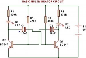
Transistors Q1 and Q2 are configured as an astable multivibrator which means one of the two transistors is always conducting. Since transistors do not conduct together, LEDs also do not glow together. When LED D1 is off, LED D2 is on and vice versa. Thus, the combination produces clock pulses.
The blinking speed of LEDs can be adjusted using capacitors C1 and C2 and resistors R1 and R2.
Mathematical formula for calculating frequency:
F = 1/T
= 1/[(0.693)*R*C]
= 1/[(0.693)*(R1*C1 +R2*C2)
where F is frequency in hertz.
R1 and R2 are resistors in Ohms.
C1 and C2 are capacitors in Farads.
T is time constant.

Multivibrator using LDR
- Now we can replace resistor R1 with an LDR and observe the change in frequency. The frequency of the multivibrator circuit now depends upon the resistance of LDR. Hence, keeping an LDR we can verify that frequency of multivibrator changes with the change in resistance. However, capacitors are also important. In the above discussion, we have found that, the frequency of multivibrator circuit depends upon the variation in resistance and capacitance. Now, we change the values of capacitors and resistors and replace LED with Piezo diaphragm and see the changes.

Mosquito repeller
After you understand the working of multivibrator, you can make a simple mosquito repeller.
When Q1 is conducting, Q2 is off and when Q2 is conducting, Q1 is off. The capacitors C2 and C3 contribute decisively to this ON/OFF cycles for the transistors Q1 and Q2. Another important factor in the operation of the circuit is the fact that the transistor goes into conduction only when the base-emitter voltage exceeds 0.7V(for silicon transistors).From the basic knowledge we can visualize how the transistors exchange their roles and the how the voltage on the collector of each transistor jumps between the upper and lower level, producing a rectangular waveform. If we take a close look at the circuit, we will see that C2 and C3 are not equal. They differ in the values by a factor of four.The output signal will thus be a nonsymmetrical waveform. Such a non- symmetrical signal contains more high frequency harmonics compared to normal square wave signal. The output of our circuit will have the basic frequency of 5Khz along with the harmonics of 10,15 and 20Khz. If some insects are deaf to frequencies upto 5Khz, they may react to 10Khz or 15Khz or even 20Khz.

🛠️ Dive into our collection of DIY Kits, 🔊 Audio Amplifiers, Digital Scoreboards, FM transmitters, and more!
🎶 Explore endless possibilities at our new store.


