


OR-gate realization
There are two LDRs kept in this circuit and the relay gets activated when light falling on any of the two LDRs is blocked. This circuit presents the working of an OR gate.


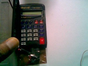
Object counter using Calculator:
To make an object counter we can use a simple dark detector circuit and a normal calculator. Pole and NO (Normally Open) terminals of a relay have to be connected to the two pins which are used to activate ‘=’ key of calculator.
As we block the light falling on LDR, the calculator starts counting.
For the calculator to work as a counter, we first need to press ‘1’ and ‘+’ keys.
All calculators may not work as counter, you need to check with the following steps:
a. First press 1
b. Then Press +
c. Then keep on pressing =
Each time when you press “=”, the calculator should increase the numbers and display 1,2,3,4… and so on. If your calculator displays “1″ every time you press “=”, then your calculator cannot be used as counter.
In our circuit, we use relay to connect two wires of ‘=’ key that eventually increases numbers on calculator.

My project

🛠️ Dive into our collection of DIY Kits, 🔊 Audio Amplifiers, Digital Scoreboards, FM transmitters, and more!
🎶 Explore endless possibilities at our new store.


on this circuit calculator swich is not a normal swich it is a pressure working dark field then how to worke this counting?
on this circuit calculator swich is not a normal swich it is just a pressure working dark field then how to worke this counting?