PWM SOLENOID AND VALVE DRIVER USING DRV103

This tiny module is a PWM Solenoids and Valves driver using Texas instrument’s DRV103 low-side DMOS power switch employing a pulse-width modulated (PWM) output. Its rugged design is optimized for driving electromechanical devices such as valves, solenoids, relays, actuators, motors and positioners. This board is also ideal for driving thermal devices such as heaters, coolers, lamps etc. PWM operation conserves power and reduces heat rise, resulting in higher reliability. In addition, adjustable PWM allows fine control of power delivered to the load. Output delay time and oscillator frequency are also externally adjustable.
The DRV103 can be set to provide a strong initial closure, automatically switching to a “soft” hold mode for power savings. A resistor, analog voltage, or Digital-to-Analog(D/A) converter can control the duty cycle. An output OK flag indicates when thermal shutdown or over current occurs.
FEATURES
- Supply 8V to 32V DC
- Load Capacity 1.5A
- Trigger Input Voltage 1.5V to 5V DC
- Thermal and Current Limit Shutdown
- On-Board Power LED
APPLICATIONS
- Solenoids
- Valves
- Heaters, Coolers
- Lamps
- Relays
- Power Contactor Coils
- Hydraulics and Pneumatics Systems
Note: PWM Duty Cycle, Output Delay, Frequency Adjust
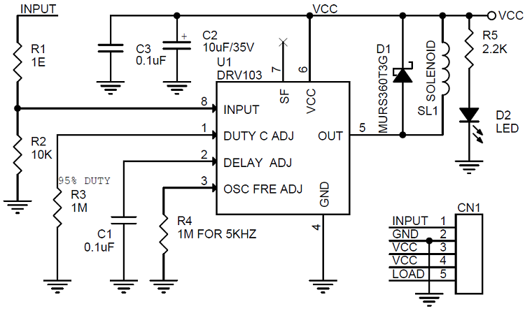
- Oscillator Frequency range 500Hz to 100Khz, the default set to 5Khz, Frequency can be altered by changing R4 ( Refer to Datasheet for more details)
- Delay Output: Default delay set to approx. 100mili seconds, Delay can be adjusted by changing Capacitor C1
- Duty Cycle is adjustable 10% to 95% , the default set to 95% can be altered by changing R3 (Refer to Datasheet for more details)
SCHEMATIC
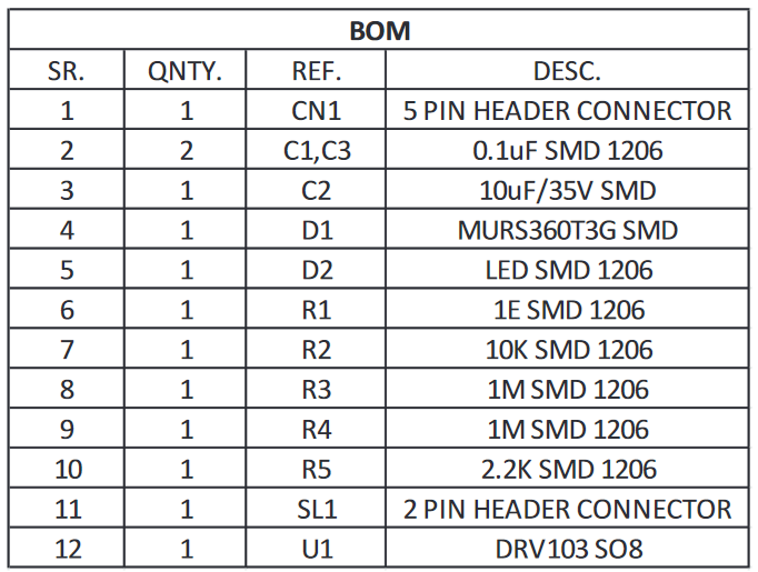
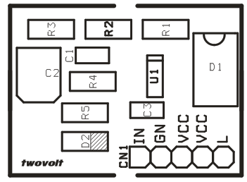
PARTS LIST
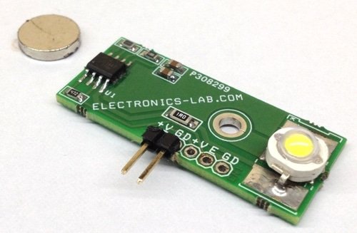
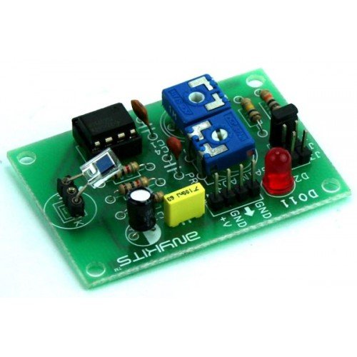
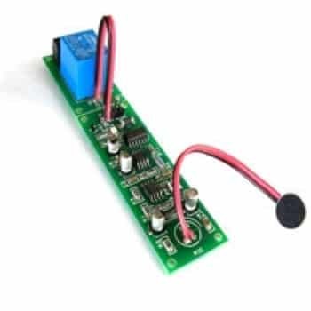
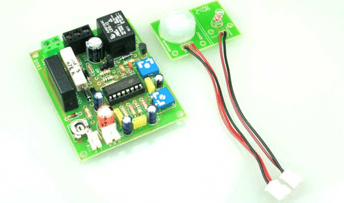
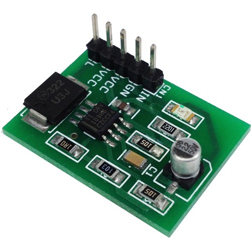
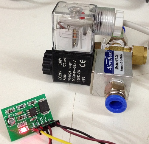
PHOTOS
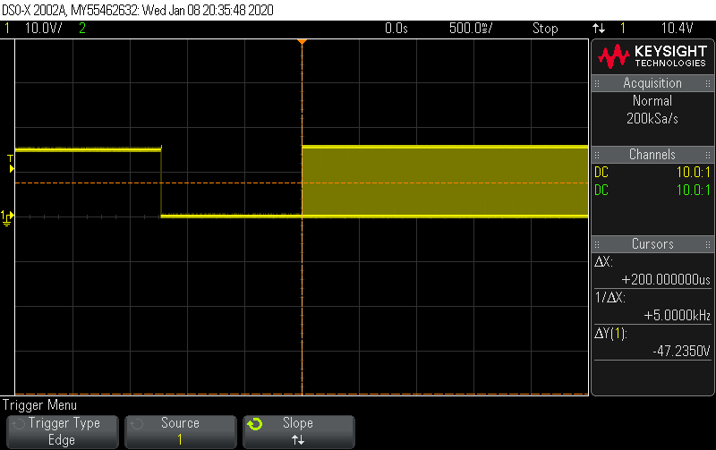
MEASUREMENTS
VIDEOS
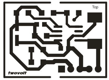
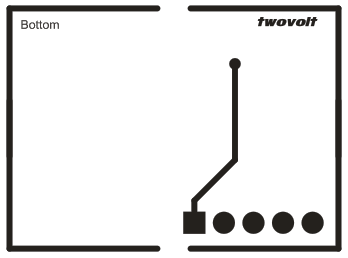
PCB
🛠️ Dive into our collection of DIY Kits, 🔊 Audio Amplifiers, Digital Scoreboards, FM transmitters, and more!
🎶 Explore endless possibilities at our new store.