


Remote operated switch DIY kit
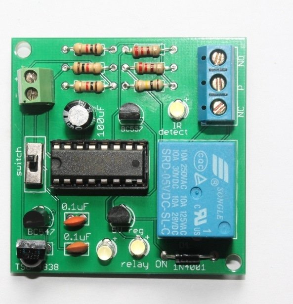
Description: Here’s a simple do-it-yourself (DIY) remote operated switch. You can use this simple kit to switch ON/OFF any appliances working on 220V AC. This DIY kit has been designed basically as a learning kit rather than as a household device. With this kit, you may learn about relay and infrared sensor. It can used for fun at home for switching appliances operating on 220V AC.
This DIY remote operated switch works with TSOP4838 infrared receiver and there is a 5V relay to operate appliances that work on 220V AC. To make the kit work, you just need a general TV/DVD remote or you can also build your own IR transmitter. The maximum distance between the kit and IR remote can be around 3 meters. Once you switch it on, it remains on until you press the remote again, which means that there are two stable states(ON and OFF).
It comes as a pack of parts kit and can be easily assembled if you can follow the silkscreen indicators (labels) and have beginning experience with a soldering iron. You will need to read the resistor bands or use a multimeter to determine the resistor sizes.
The kit operates with a 9V power supply.
![]()
Features:
- The distance between the IR transmitter(TV/DVD remote) and receiver kit can be around 3 meters.
- The kit can be operated with any kind of remote control. Therefore, it can also be used as a remote tester.
Kit package contains:
- 1 x TO-92 5V Voltage Regulator(78L05)
- 1 x CD4017 Decade counter
- 1 x 16-pin IC socket.
- 1 x TSOP4838 Infrared sensor
- 1 x 100uF Capacitor- (Voltage rating can be between 16V to 50V- causes no problem in operation)
- 2 x 0.1uF 50V ceramic Capacitor
- 3 x 3mm LED- (can be any color)
- 1 x BC547
- 1 x BC557
- 1 x SPDT Slide Switch
- 1 x 2 pin Screw terminal- (can be in blue/green colors)- For power supply.
- 1 x 3 pin Screw terminal- can be in blue/green colors- Connects to relay.
- 3 x 1K Ohm Resistor 1/4W
- 2 x 220R Resistor 1/4W
- 1 x 100K Ohm Resistor 1/4W
- 1 x 5V relay
- 1 x 1N4007 diode
- 1 x Bare PCB with Silkscreen Indicators
Schematic:

![]()
Working: When you press any switch on your remote, the infrared sensor gets triggered(gives LOW output) and it feeds pulse to CD4017 via BC557 transistor. To feed the pulse for a while, RC circuit has been formed by C1(100uF) and R4(100k). The CD4017 has been configured to operated as a toggle switch. When LED1 is on, LED3 is off and vice versa. LED3 also indicates that the relay is on.
CD4017 is a decade counter that can be configured to operated as a toggle switch.
Documents:
- About remote operated DIY kit
- Assembly tutorial
- How to connect appliances to the kit- CAN BE DANGEROUS. DON’T TRY THIS IF YOU DON’T KNOW ABOUT RELAYS.
- Schematic
- Flickr Images
- Video 1– Operating with IR transmitter. You can make your own infrared transmitter using NE555. Get project details from buildcircuit.com. Check out this tutorial also.
- Video 2– Operating the kit with a TV remote control.
- Video 3– Operating the kit with remote control.
![]()
🛠️ Dive into our collection of DIY Kits, 🔊 Audio Amplifiers, Digital Scoreboards, FM transmitters, and more!
🎶 Explore endless possibilities at our new store.


With this kit, do i have to connect the two 3mm LED lights? Are they necessary to make the kit work? I wouldn’t like to have the LED lights on the whole time. Thanks
This is a good and excellent circuit .
I have built this infra red circuit and works no problems until I connect the relay although the led’s shows on and off when clicking tv remote but seems no power going to relay although reads power on multimeter and just for temporary installed resistor and led on power leads to relay and led lights up and switches off when clicking tv remote. any ideas please. thanks
i made the same circuit, the ir sensor senses but does not turn on the relay??
what should be the actual input voltage