


Remote Operated Switch
To make a remote operated switch, you need to understand following circuits. I recommend you to make these circuits before you try a remote operated switch. a. Toggle switch using 555.
b. Dark sensor using two transistors.
d. Light operated switch
e. Monostable mode of operation of 555
f. How to use TSOP(infrared sensor)
Description of remote operated switch
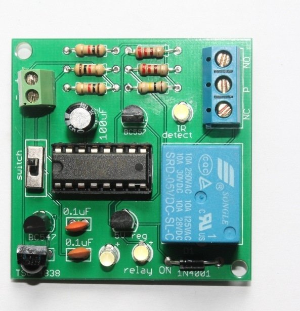
When you press an infrared transmitter or normal TV remote control near TSOP1738 infrared sensor, the 555 timer configured in monostable mode gets triggered. The output pin 3 of 555 timer remains on for a while and the ‘on time’ is determined by the resistor R2 and capacitor C1. The output at pin3 along with transistor BD139 activates the 6Vrelay. The relay switches on the 555 timer configured in toggle switch mode and that finally glows LED D2. When you press remote control again near TSOP1738, the LED D2 switches off.  Fig. Remote operated switch(Click on the schematic to enlarge it)
This project was tested and verified during LDR Engineering Course.
🛠️ Dive into our collection of DIY Kits, 🔊 Audio Amplifiers, Digital Scoreboards, FM transmitters, and more!
🎶 Explore endless possibilities at our new store.


HI SIR
I THINK THIS TSOP 1738 IC (INFRARED RECIVER) CAN TAKE FROM OUR SCRAP TV,DVD.
ALSO
CAN I MAKE MY OWN INFRARED TRANSMETER.(WITH REGULAR PUSH BUTOONS)
Yes, definitely, you can get it from your scrap TV, DVD, it’s the same. But just be careful with the right 5V, GND and OUTPUT pins, it can be different from the one I have used. And second thing, you can make your own infrared transmitter also, here is the link for that: http://www.buildcircuit.com/astable-mode-of-555-timer/
explain the circuit more precisely.
Can i use any other transistor in place of BD139?
Sir,
instead of adding the toggle switch (using 2nd NE555 ) at the relays end can i directly apply it to load incase i don’t want to glow led ?
I have build it 2 days ago.Just working fine….thanks sir.
Nice tutorial…thanks very much, THANK YOU!!
Sir,
instead of adding the toggle switch (using 2nd NE555 ) at the relays end can i directly apply it to load incase i don’t want to glow led ? –
sir please tell how to control the 2 lights with remote send the circuit my mail id sir….
How to use this circuit for home appliances.