Assembly guide- DIY Arduino

We are now selling the BLUE COLORED DIY Arduino kit
This post shows you how to assemble the DIY Arduino board.
The assembly process is straight forward. It can be easily assembled if you follow the silkscreen indicators(labels) and have beginning experience with a soldering iron. You will need to read the resistor bands or use a multimeter to determine the resistor sizes.
Note: You will need either an FTDI Basic or FTDI cable to load code using the Arduino IDE.
Kit Includes:
- 1 x Arduino-Compatible plated through holes (PTH) Kit PCB
- 1 x ATMega328 with Optiboot bootloader
- 1 x L78L33 3.3V Voltage Regulator
- 1 x 5mm Green LED
- 1 x 5mm Red LED
- 2 x 330Ohm Resistor
- 1 x 10kOhm Resistor
- 1 x 16MHz Crystal
- 2 x 22pF Ceramic Capacitors
- 5 x 0.1uF Ceramic Capacitors
- 2 x 10uF Electrolytic Capacitors
- 1 x LM7805 5V Regulator
- 1 x Diode 1N4001
- 1 x Resettable Fuse PTC (300mA)
- 1 x 28-Pin DIP Socket (To seat your ATMega)
- 1 x Push Button Reset Switch
- 2 x 6-Pin Female Headers
- 2 x 8-Pin Female Headers
- 1 x 6-Pin Right Angle Header (To connect your FTDI Basic)
- 1 x 0.1uF Capacitor
- 1 x DC Barrel Jack
- 1 x 2-pin screw terminal
- 1 x 6 pin ICSP header

Description of this DIY Arduino board is available on this page.
Assembly video:
See all the assembly images on Flickr
You can see all the assembly steps on this post.
Step 1: Start with the resistors 10K(Brown-Black-Orange) and 2 pcs 330R (Orange-Orange-Brown).

You can see all the assembly steps on this post.
Step 2: Then fix the 16Mhz crystal oscillator, 1N4001 diode and 2pcs of 22pF capacitors.

You can see all the assembly steps on this post.
Step 3: Fix 5 pcs of 0.1uF capacitor. The image shows only 4pcs. I actually forgot to solder the last one, which is right after the Vin point.


Step 4: Solder LM7805 voltage regulator, 3.3V regulator and the tactile switch.

You can see all the assembly steps on this post.
Step 5: Now fix the PTC resettable fuse (300mA), 28pin IC header, 2 pin screw terminal and 2pcs of 5mm LEDs.

You can see all the assembly steps on this post.
Step 6: Fix the DC barrel, 2 pcs 10uF capacitors, 6 pin male header (for connecting FTDI basic module) and ICSP header.
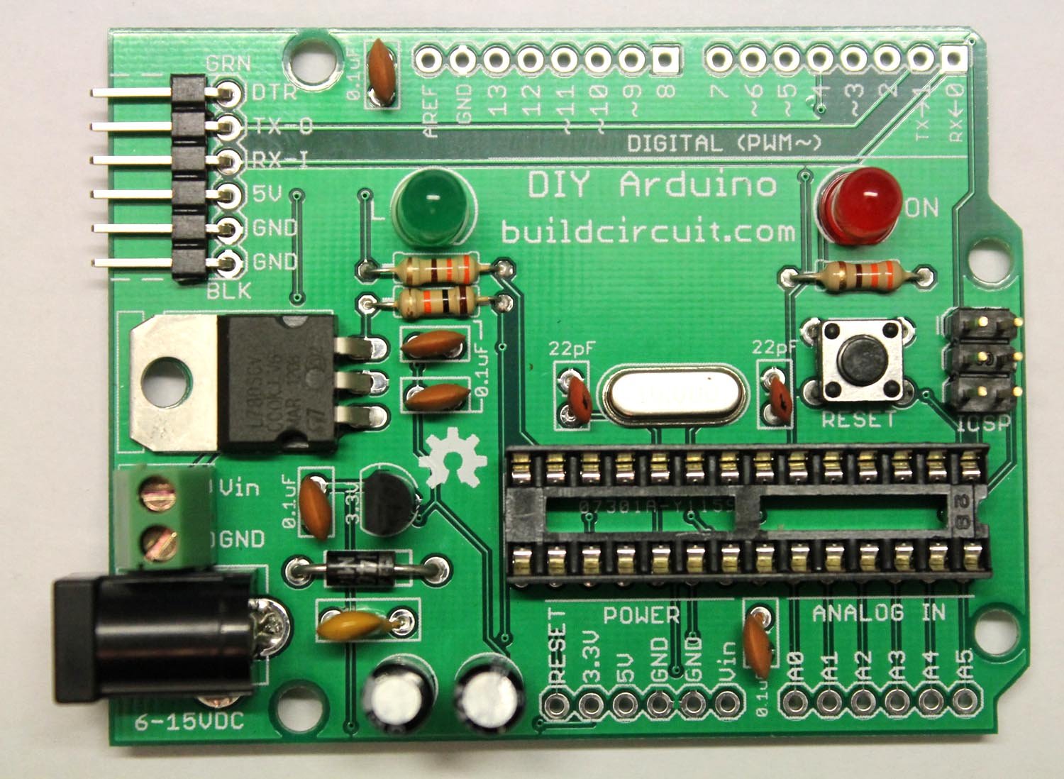
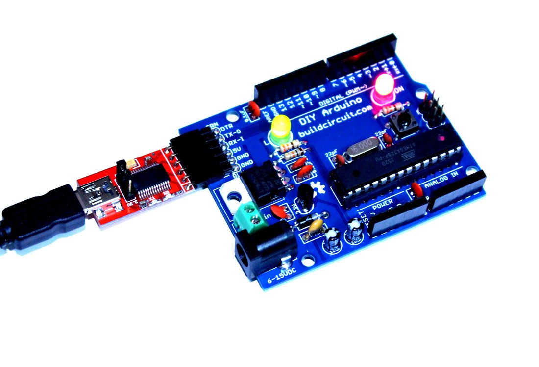
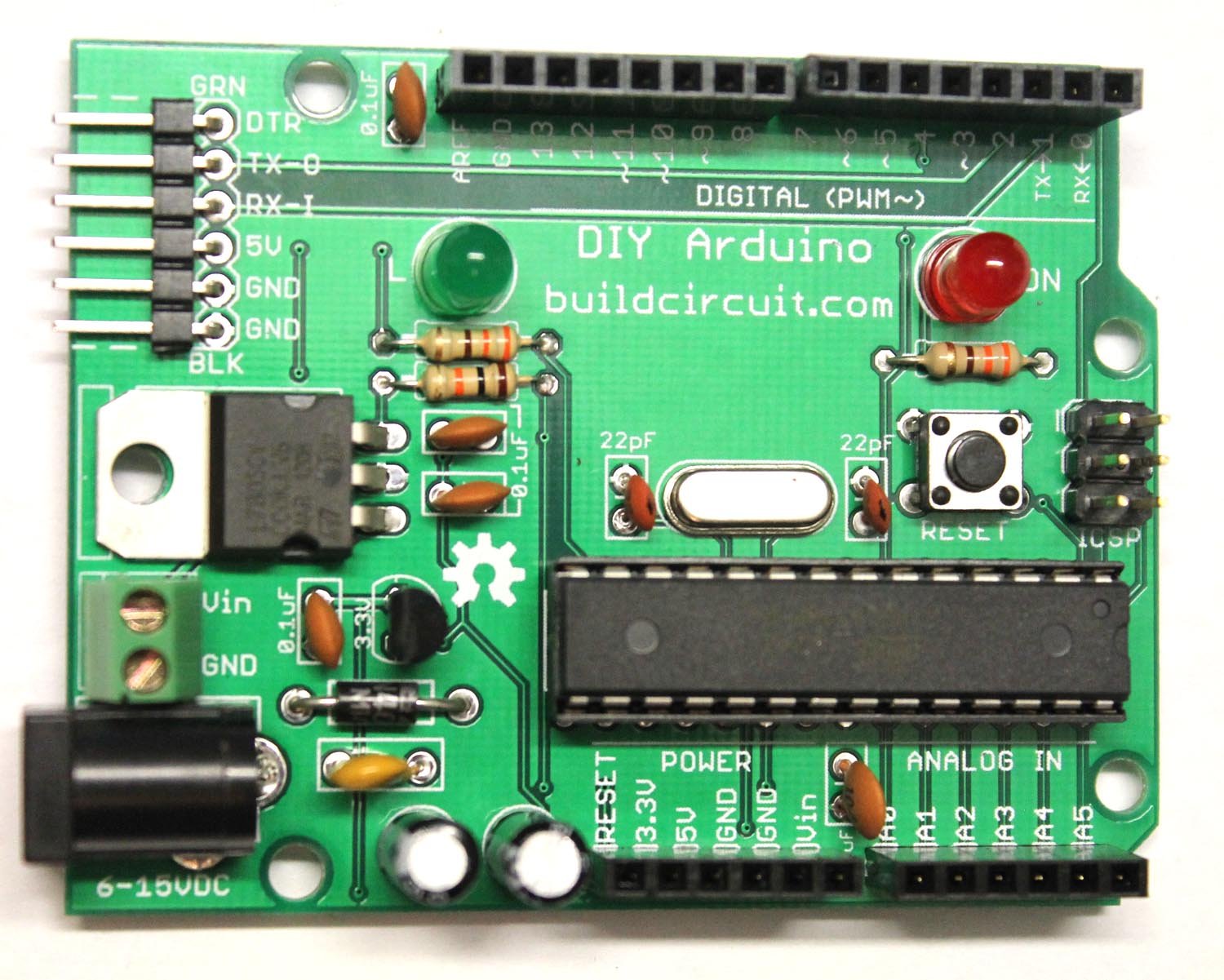
Step 7: Finally, fix the stackable headers and Arduino UNO chip. Your Arduino is now ready.
You would need a FTDI basic module to program the Arduino board. The following image shows how to connect the FTDI basic module.
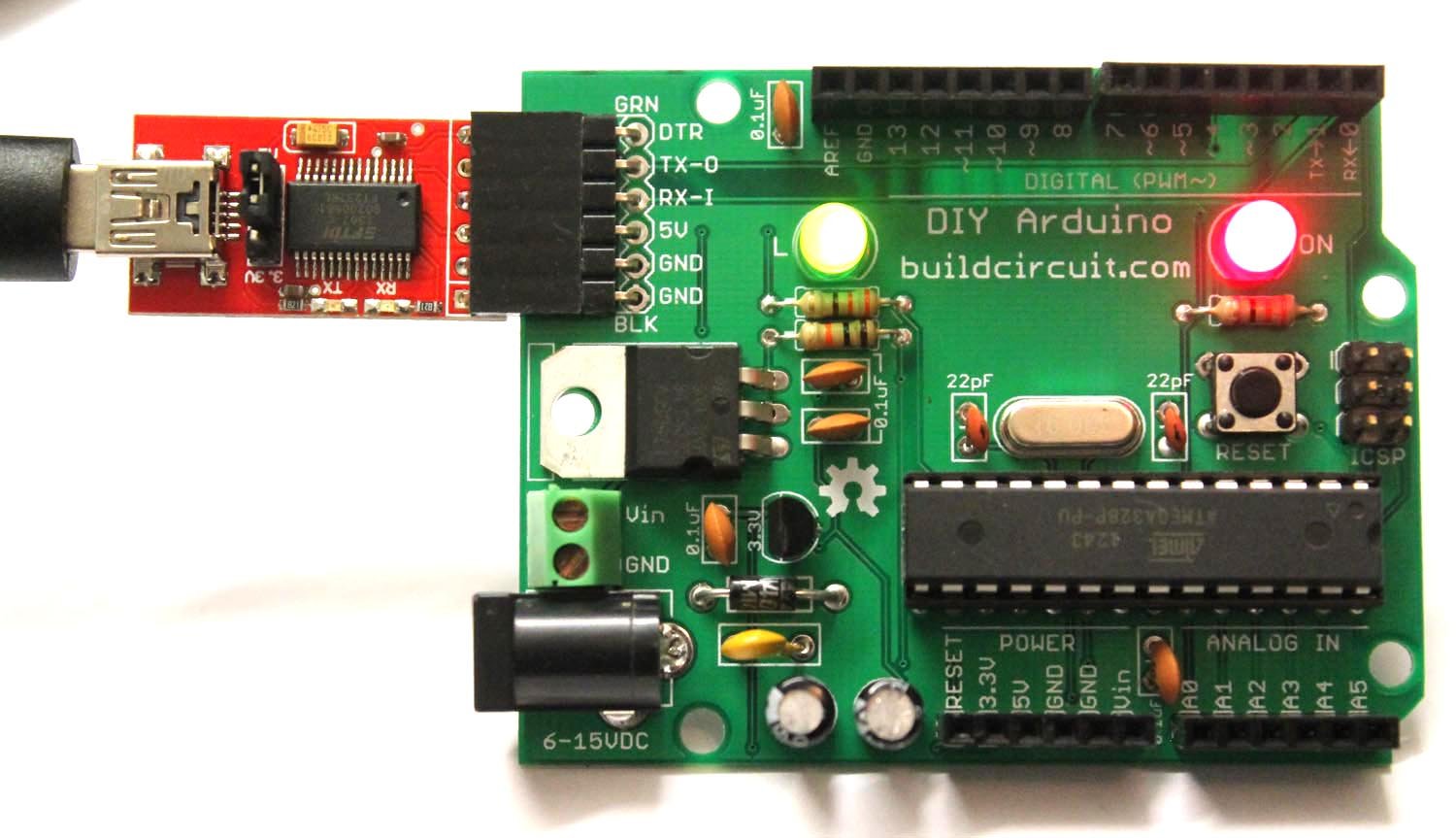
You can see all the assembly steps on this post.
See all the assembly images on Flickr
See the output below:
🛠️ Dive into our collection of DIY Kits, 🔊 Audio Amplifiers, Digital Scoreboards, FM transmitters, and more!
🎶 Explore endless possibilities at our new store.