


Building a circuit on a breadboard

A breadboard is a device for testing temporary electronics projects. Components used to test a circuit can be reused for other projects. None of the components are damaged.
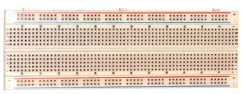
Almost all people start to learn electronics using breadboard because it is the simplest way of making circuit. The photograph shows a typical small breadboard which is suitable for beginners building simple circuits with one or two ICs (chips).
Connections on Breadboard
Breadboard has many tiny sockets or holes arranged on a 0.1’’ grid. The leads or terminals of most of the components like resistors, diodes, transistors, etc. can be pushed straight into the holes.
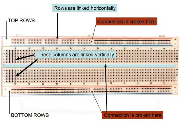
A breadboard has 4 rows of holes at the top and 4 rows at the bottom and there are several columns of holes in the middle.
There are two groups of vertical columns in the middle part, as you see in the picture below it has been separated by a blue rectangular block.
None of the rows and columns are linked to one another.
The holes in rows are linked horizontally and column holes are linked vertically.
Converting a circuit diagram to a breadboard layout is not straight forward because the arrangement of components on breadboard looks quite different from the circuit diagram. When putting parts on breadboard you must concentrate on their connections, not their positions on the circuit diagram.
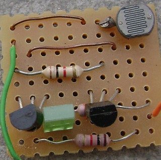
Building a Circuit on Breadboard(Dark Detector using transistor)
Get following components:
NPN transistor- BC547 or BC147 or BC548
![]()
![]()
Resistor- 100K
![]()
Resistor-330Ohm
![]()
Light emitting diode(LED)

Light dependent resistor(LDR)

Connecting wires- Use single-core plastic-coated wire of 0.6mm diameter (the standard size)-You can use wire that is used for Computer Networking.

6V battery (4 -AA size battery)
🛠️ Dive into our collection of DIY Kits, 🔊 Audio Amplifiers, Digital Scoreboards, FM transmitters, and more!
🎶 Explore endless possibilities at our new store.


Very good presentation. Very basic but also very interestin.
Keep up the Good Work!
Jack
yar is circuit ki bread board pe connection to bta do plzzz
Very good for beginners..
Very very useful.
Thank you very much..
super sir pls mail updates to me because i am veerly intereested plssssssssssssssssssssssssssssssssssssssssssssssssssssssssssss sir sir
subscribe from here: http://feedburner.google.com/fb/a/mailverify?uri=BuildCircuit
Very good for beginners
I am going to use this system to lock and ulcnok the door and turn on and off all utilities (like electricity and internet) to my home datacenter that operates a network for my entire street as well as my small business.
wonder full sir thank you very much sir
great one sir,Thanks very much
Thank you sir for providing such amazing information.
It really helps for us type begineers
Awesome………!!!!!!!!!!!! Thanj youuuuuuu……….!!!!!!!!!!
Very useful for beginners
Very useful…
nicely explained! 🙂
Simple Explanation about breadboard
It is useful for all students who start career in Electeronics
Well explanatory for amateur…..kudos!!!
very useful for every one.
Excellent explanation! Thanks
my friend, there are a good article.
can plese help me to switch on the ldr in morning and switch off in the night
Sir your projects from absolute beginners are very helpful. However, I shall be grateful if you could demonstrate a step to step circuit on breadboard as to how to build a digital clock. The circuit may be very simple as I am absolute beginner.
I am sorry. I have no time to do that 🙁 .
You should be a part of a contest for one of the most useful sites on the web. I most certainly will recommend this web site!
plz post its bread board connections
Hello,
Interesting Tutiorial.
Can you post the same circuit if I am using a 12v dc power supply to light a 12 V led bulb?
Thanks in advance.
Good article thanks for sharing that!!!
domain to look http://blahc-blahc.net
sir can I use a 9v battery instead of 6.plz replay..
I seriously need help on ma project…. That is building a dark operating switch… Hv no idea and I greatly require your assistance
Thank you for this. I added an indicator LED to show that the circuit is ON (even when it is in the light). I used a tri-color LED that morphs from Red to Green to Blue every few seconds, very attractive. Like these:
http://www.ebay.com/itm/290687687407?_trksid=p2057872.m2749.l2649&ssPageName=STRK%3AMEBIDX%3AIT
I connected it across the + and – of the battery. Since my entire circuit is on a switch (the Automatic setting of a Lo-Hi-Auto selector switch) the indicator LED only runs when the flashlight is in Automatic mode.
It is great but why you use that 100k Ohm resistor? Everything can happen without it… pls somebody explain me.