


Easy steps for making a line following robot using Infrared LED, Photodiode, Ardumoto and Arduino.
DOWNLOAD IN PDF- LINE FOLLOWING ROBOT USING ARDUINO AND INFRARED LED
This project has been derived from LDR based line following robot. I strongly recommend that you first try line follower robot using LDR, I found that the LDR gives better results than infrared sensor.
We need the following components for making a line following robot using Infrared sensors.
1 . Arduino- obviously !
2. Ardumoto – You can buy one from buildcircuit.net. BUY NOW.
3. A robot chassis- you can buy one from sparkfun.com or from this link: 70108 Tracked Vehicle Chassis
4. 3x Current limiting resistors: 220Ohm.
5. 3×10 kOhm resistors.
6. 3 x Infrared LEDs- BUY NOW
7. 3x Photodiode- How to use a photo diode?
8. 2 x DC motors- If you get a magician chassis from sparkfun, you get 2 DC motors along with the robot chassis.
9. Battery pack- 6V
10. Wires/connectors.
What is the logic behind a line following robot?
There are basically two ways of building a line following robot. First, using a light dependent resistor(LDR) and second, using Infrared(IR) LED. A dark object reflects less light than a bright object, or we can also say, a dark object absorbs more light than a bright object, this is the only fundamental logic behind a line sensing robot. So, in a line sensing robot, we make a sensor that detects the difference between bright object and a dark object, or say, distinguishes a black line from a white surface.
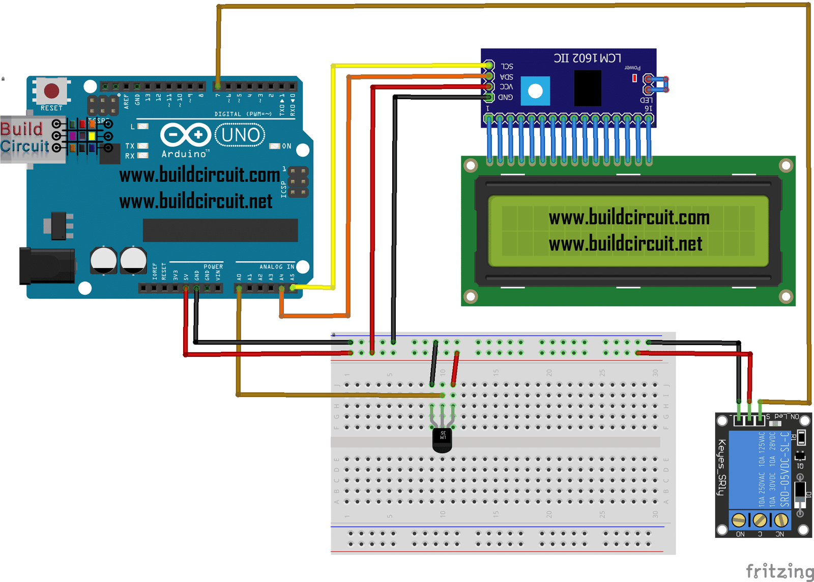
The circuit for making Infrared based line sensing robot:

![]()
If you have never worked with Ardumoto or Infrared, follow these links:
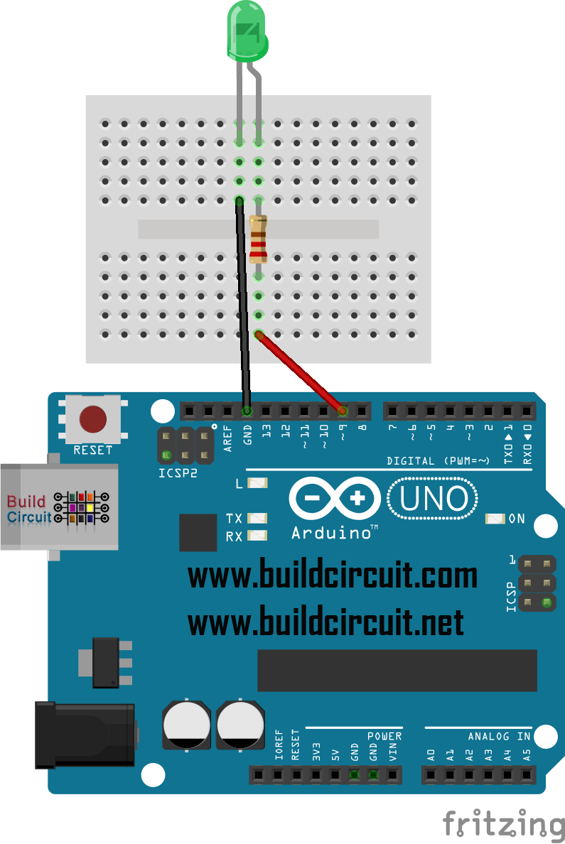
Test your sensor
Before you start assembling the sensor onto your robot chassis, check your if your sensor is detecting the black and white surfaces properly. I have written a post about testing the sensor, FOLLOW THIS LINK.
How to assemble?
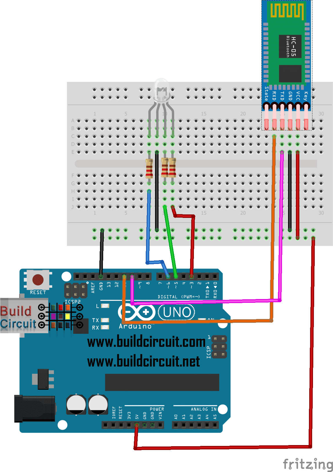
The most difficult part of this project is to make a combination of Infrared LEDs and Photo diodes. In this project, I used a mini breadboard, whereas in case of LDR based robot, I have used PCB.
Fix the components as shown in the picture:
")
")
Second important thing you should remember is that the photo diodes should be slightly above the Infrared LEDs, so that the rays don’t fall directly on the photo diodes.
Now, connecting the sensor circuit to Arduino pins:
Just follow the picture shown below:
")
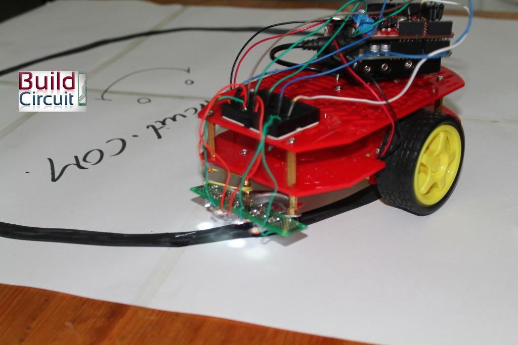
Your sensor should be around 5-7mm above the black line.
")
The turns should be made smooth, not sharp because the photo diodes won’t sense quick transition. I have made a circular path. And I made the black line using a black board marker, you can try with electric tape also.
")
DOWNLOAD IN PDF- LINE FOLLOWING ROBOT USING ARDUINO AND INFRARED LED
HOW TO MAKE LINE SENSING ROBOT USING LDR
![]()
🛠️ Dive into our collection of DIY Kits, 🔊 Audio Amplifiers, Digital Scoreboards, FM transmitters, and more!
🎶 Explore endless possibilities at our new store.

I have a slight problem. When I put a 9V dc battery as supply to the bot and enable the motors then after 5-6 mins the IR sensors’ ability to detect the surface, from the same distance as set earlier, decreases. I have been trying to sought out the issue but need some guidance. Can anybody help me out?
not like i can help you, i mean it’s 2 years ago.
9V battery (box) have less capacity (idk 3digits mAh) than 4 AA battery (about early 4 digit mAh EACH), so more likely that the supply wasn’t enough at that time.
it’s just in case you use box 9V battery
“Easy steps for making a line following robot using Infrared LED, Photodiode,
Ardumoto and Arduino. | BUILD CIRCUIT” was in fact a fantastic posting.
If only there were considerably more blogs similar to this excellent one in
the actual the net. Regardless, thanks for your time, Lucile
Can i make it with pcb or vero board instead of using arduino board?
got it
yes. But, you need you have an Ardunio microcontroller on it. So, it’s better to get an Arduino board, that will make it easier.
Hi, what was the values returned by the reflection sensor?
the variable lights .. what is the use of it
how would u do it using the tracked Vehicle Chassis?
how woyld u do it with the tracked Vehicle Chassis
Hi, can some1 send me the assembly schematic for this robot ? thx in advance
hey,if we are using arduino,what is the code required to run the robot?
Is code required?
Easy steps for making a line following robot using Infrared LED, Photodiode, Ardumoto and Arduino. | BUILD CIRCUIT
Christian Louboutin Balacorta http://www.hecht.org/sneakers/christian-louboutin-balacorta.html
Easy steps for making a line following robot using Infrared LED, Photodiode, Ardumoto and Arduino. | BUILD CIRCUIT
sweat jordan homme http://www.tableau-noir.net/miroir/sweat-jordan-homme.html
Easy steps for making a line following robot using Infrared LED, Photodiode, Ardumoto and Arduino. | Site for electronics hobbyists and engineers
canada goose avis http://www.rickspicks.ca/vancouver/canada-goose-avis.html
Need circuit diagram .