How to assemble Amarino Evaluation Shield
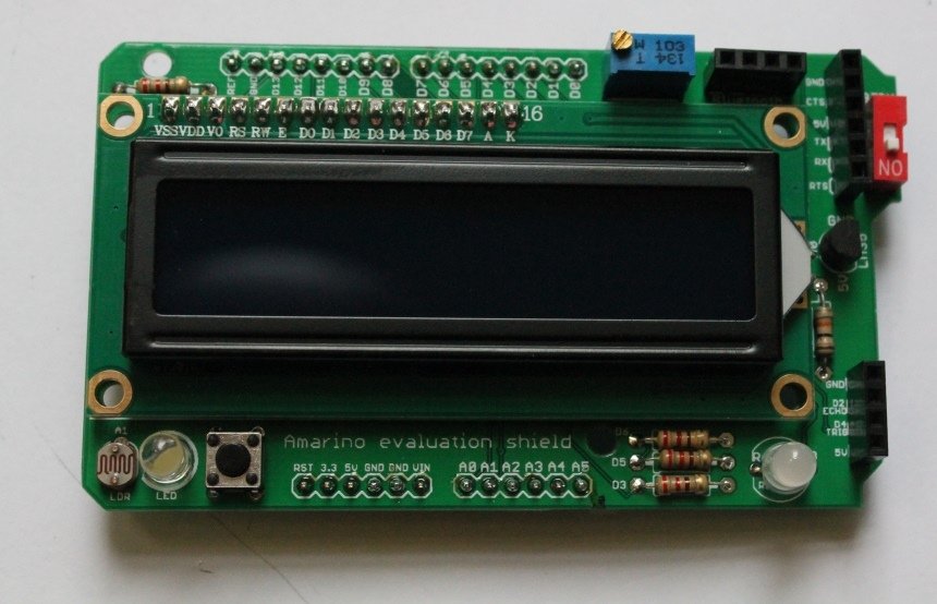
SEE ALL THE PHOTOS ON FLICKR This post shows you how to build the Amarino evaluation shield.
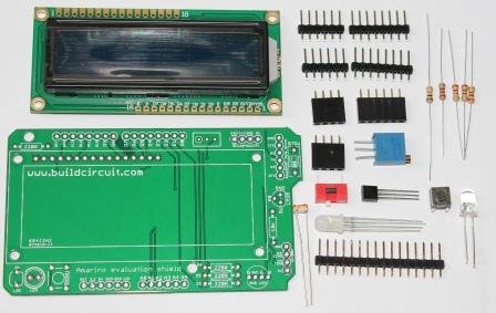
When you buy the shield package, you will get the following components.
Fully assembled kit is now available on buildcircuit.net.
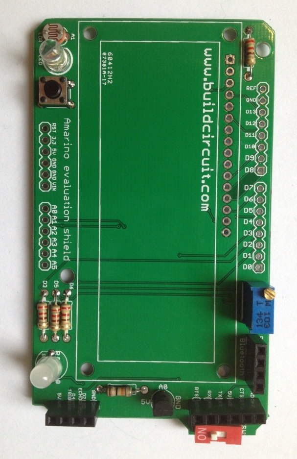
The PCB:
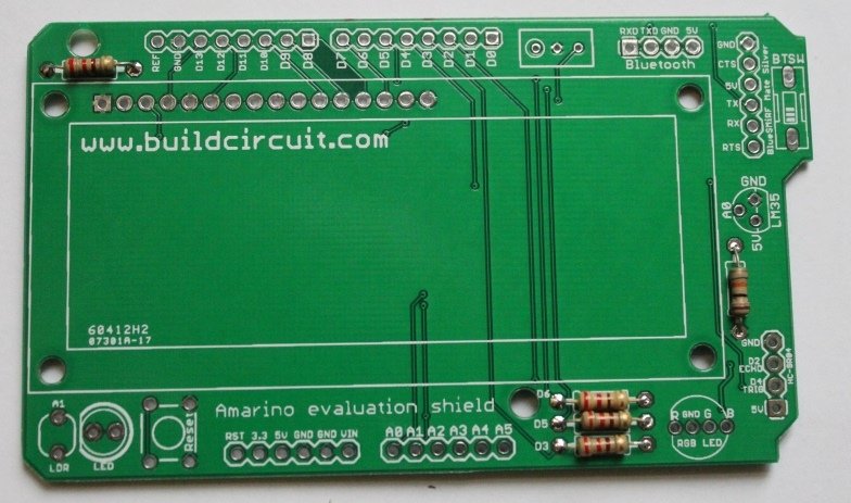
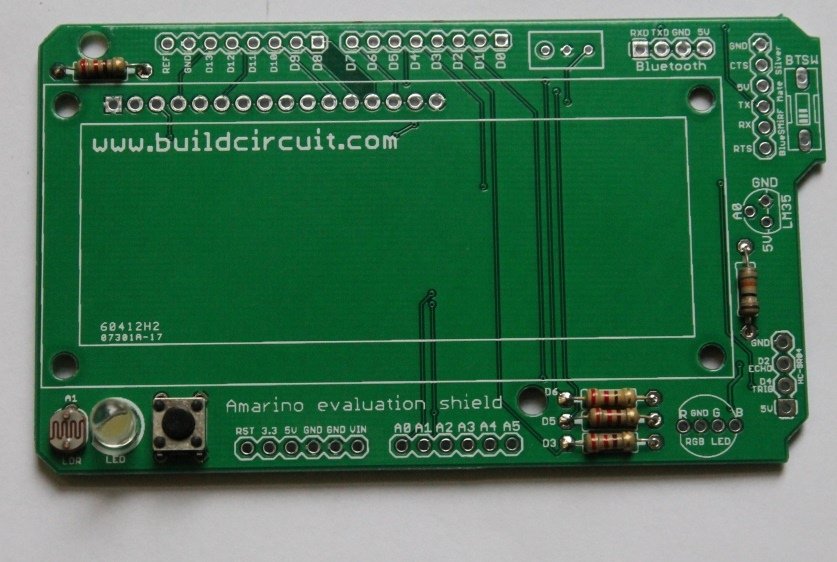
PCB clearly shows the pin and component names, so, it should help you to get idea of connections of components to Arduino. If you just follow the names of components on the PCB, it is possible to assemble the whole kit without reading the rest of this post. However, I have shown all the important steps.
Step 1: Always start with the smallest component. So, start with resistors. Fix resistors 220R. 
Step 2: Then fix 10k resistor.
Step 3: Then, fix LDR and 5mm white LED.
Step 4: Fix tactile switch
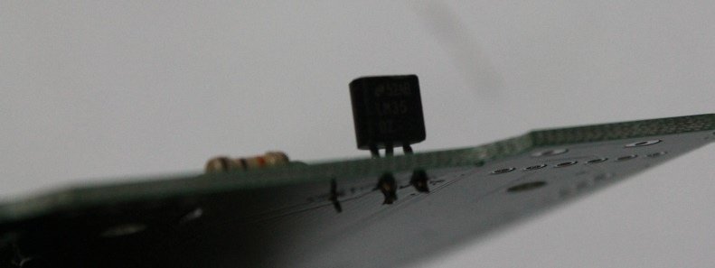
Step 5: Fix LM35.
Step 6: Fix RGB LED. It is common cathode type RGB LED.
Step 7: Solder all the female headers.
Step 8: Solder 10k variable resistor and 1 position DIP switch,
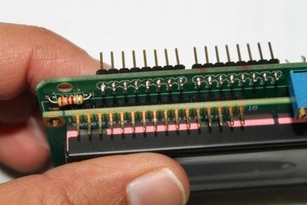
Step 9: Fix 16×2 LCD. While soldering the header the 16×2 LCD, the longer part of header should be on the upper side of PCB. Please see the picture below:
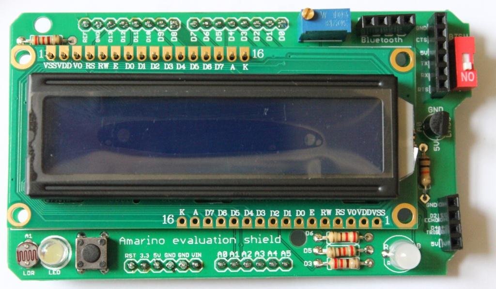
When you purchase the kit, you may get a slightly different LCD that needs to be fixed in the following way:
Step 10: Solder 4 pcs of male headers on the PCB to stack the shield over the Arduino.
Your shield is ready 🙂 .
Stacking adapter: You can stack either BlueSMiRF mate silver or general Bluetooth adapter over the shield. See the following pictures how they are stacked.
First Experiment: Test if the LCD is working- source code Download source code Watch the video to know how to change the contrast level of LCD. Move the 10k variable resistor screw in the clockwise direction to increase the contrast level. After you confirm that the LCD is working, modify the source to test RGB LED, LDR, LM35DZ and 5mm LED. Check the schematic and circuit layout.
Check out all the experiments with Amarino Evaluation shield
Fully assembled kit is now available on buildcircuit.net. Watch all the videos (Playlist):


